Before starting the project, we decided to submit two ideas each.We chose Idea #1, as it requires few components, yet has a beautiful result.
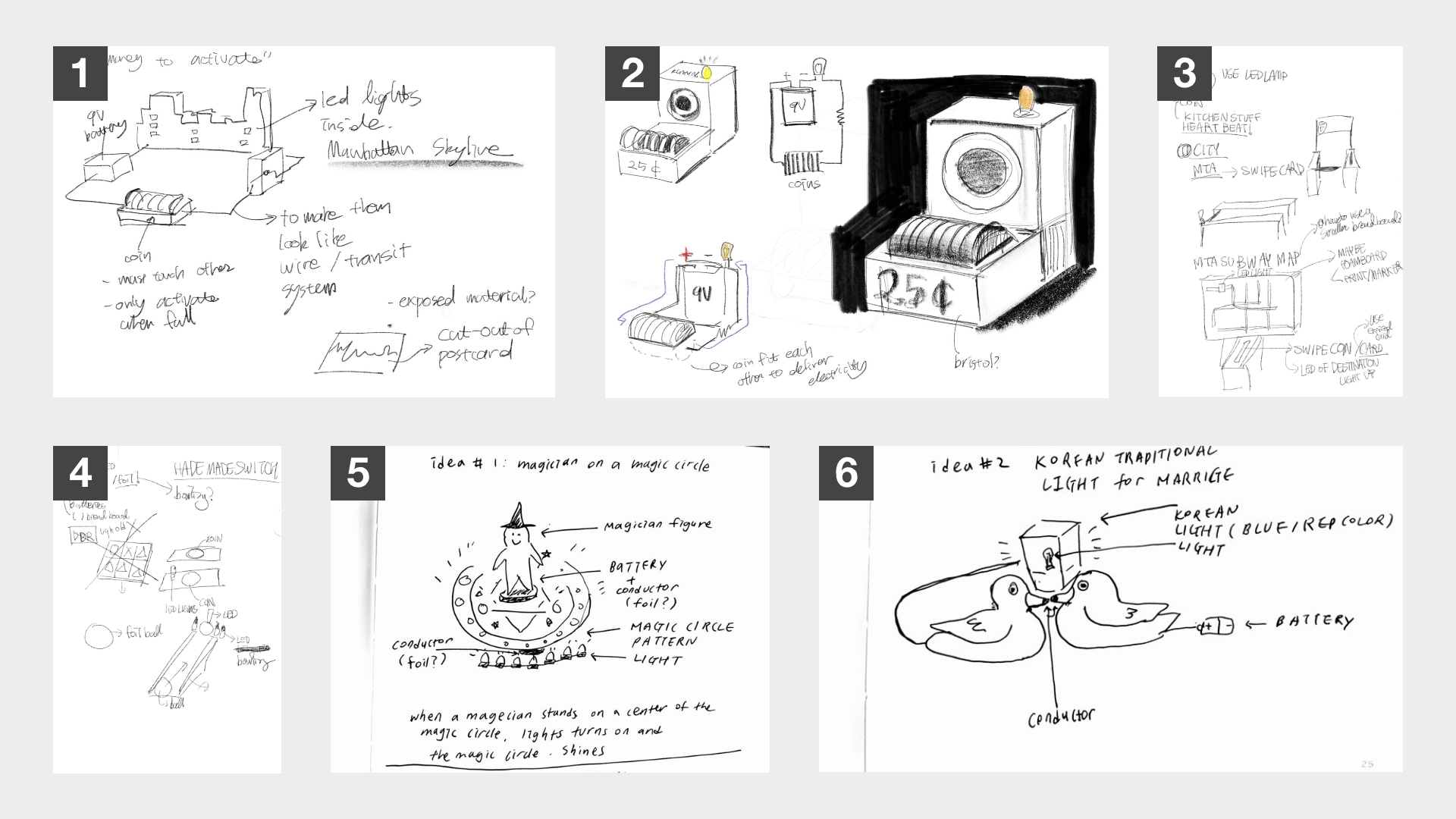
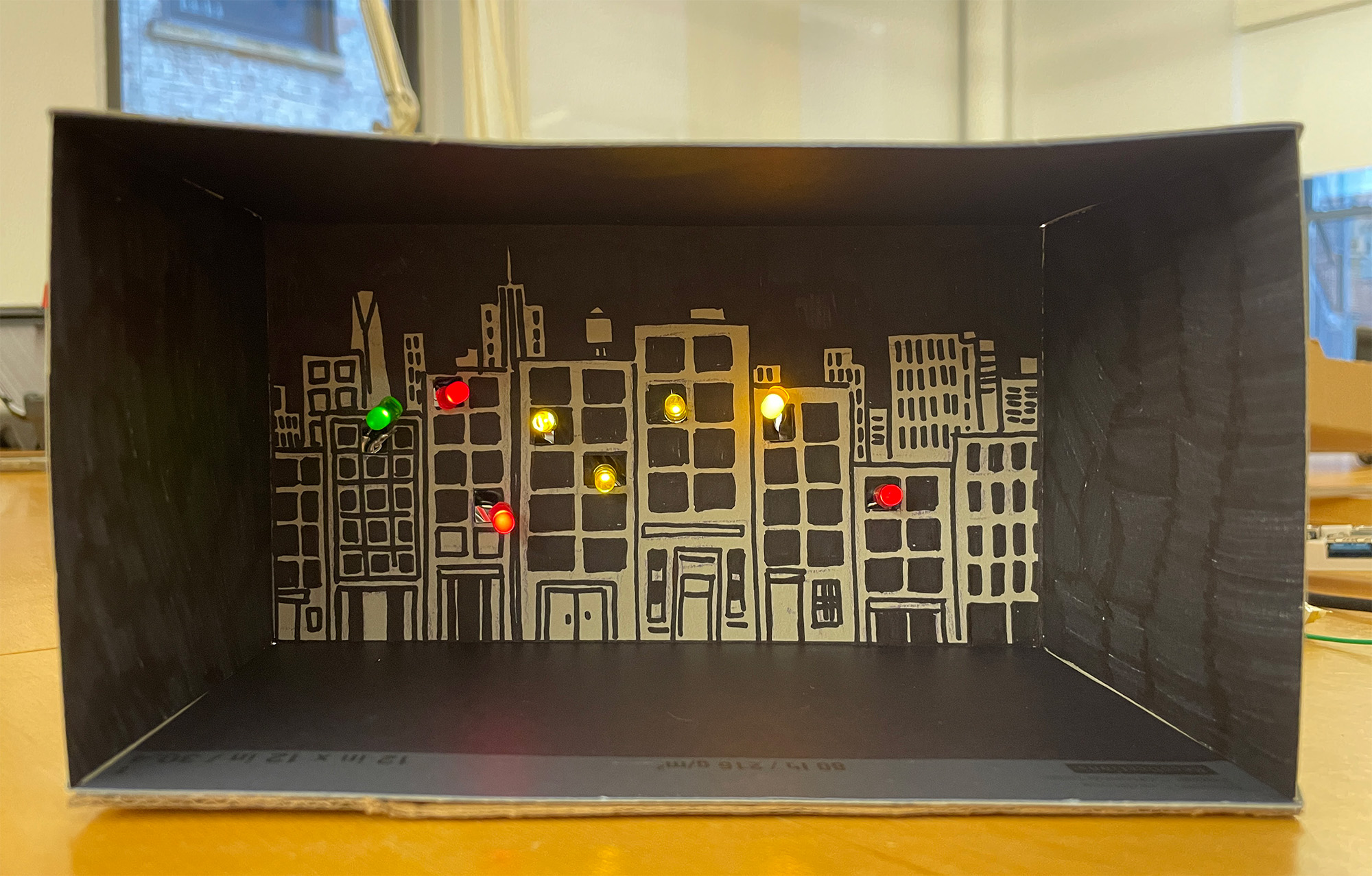
When we first got the assignment to make a homemade switch with LED lights, the night view of Manhattan's night view came to mind. We came up with the concept of 'paying 50 cents to see Manhattan's at night view'. Then we decided to use LED lights to make the skylineManhattan's night view and to use a coin as a conductor. The coin would be used as a switch to turn on the light.
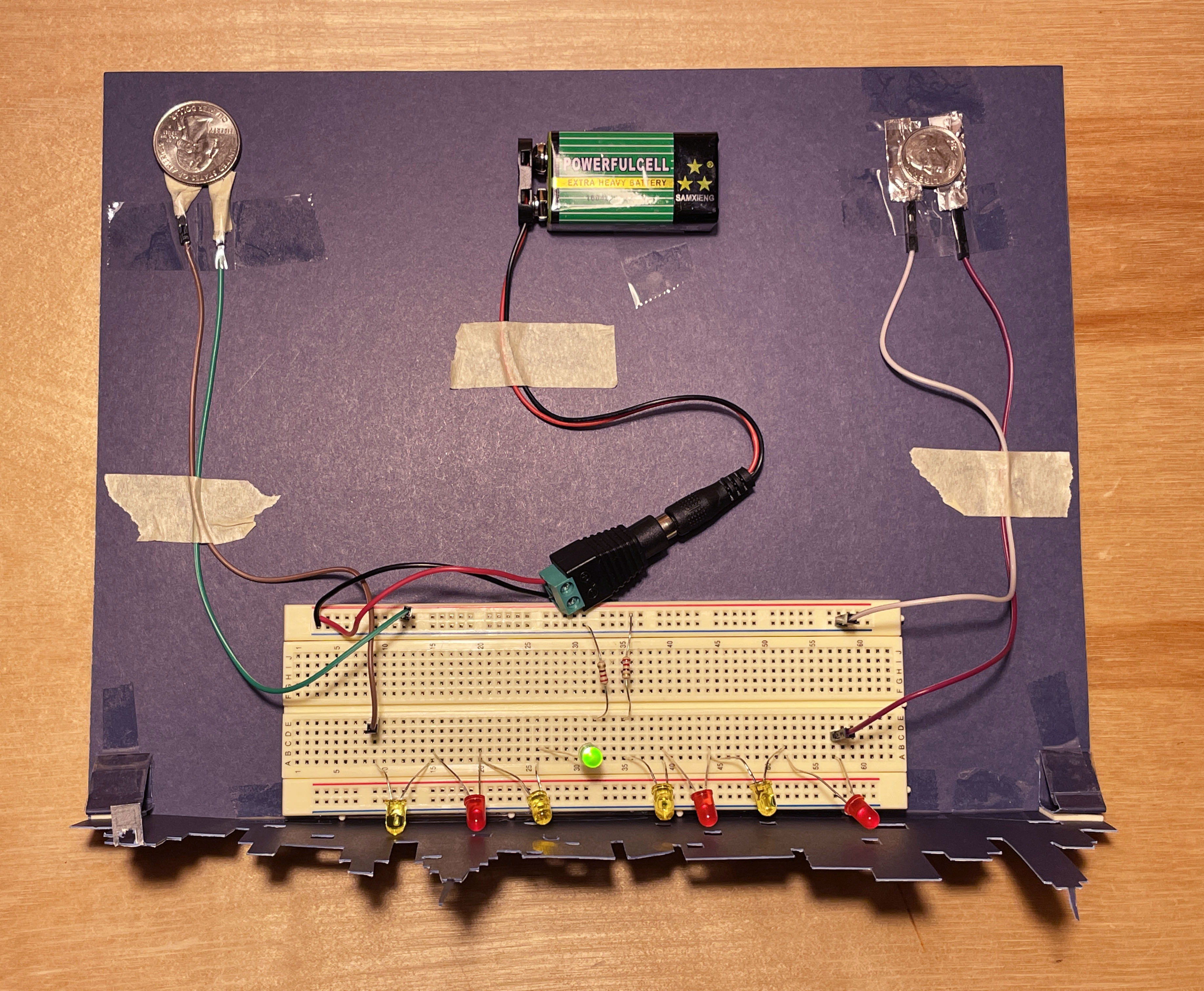
Coin, 9V battery, 220Ω resistor, LED lights, black paper, aluminum foil, and illustration of Manhattan buildings.
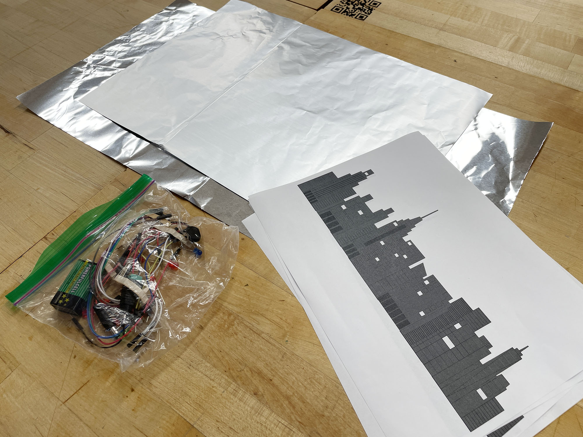
Before we proceeded withon making the switch, we drew an illustration of the Manhattan landscape that would become our base for this project.

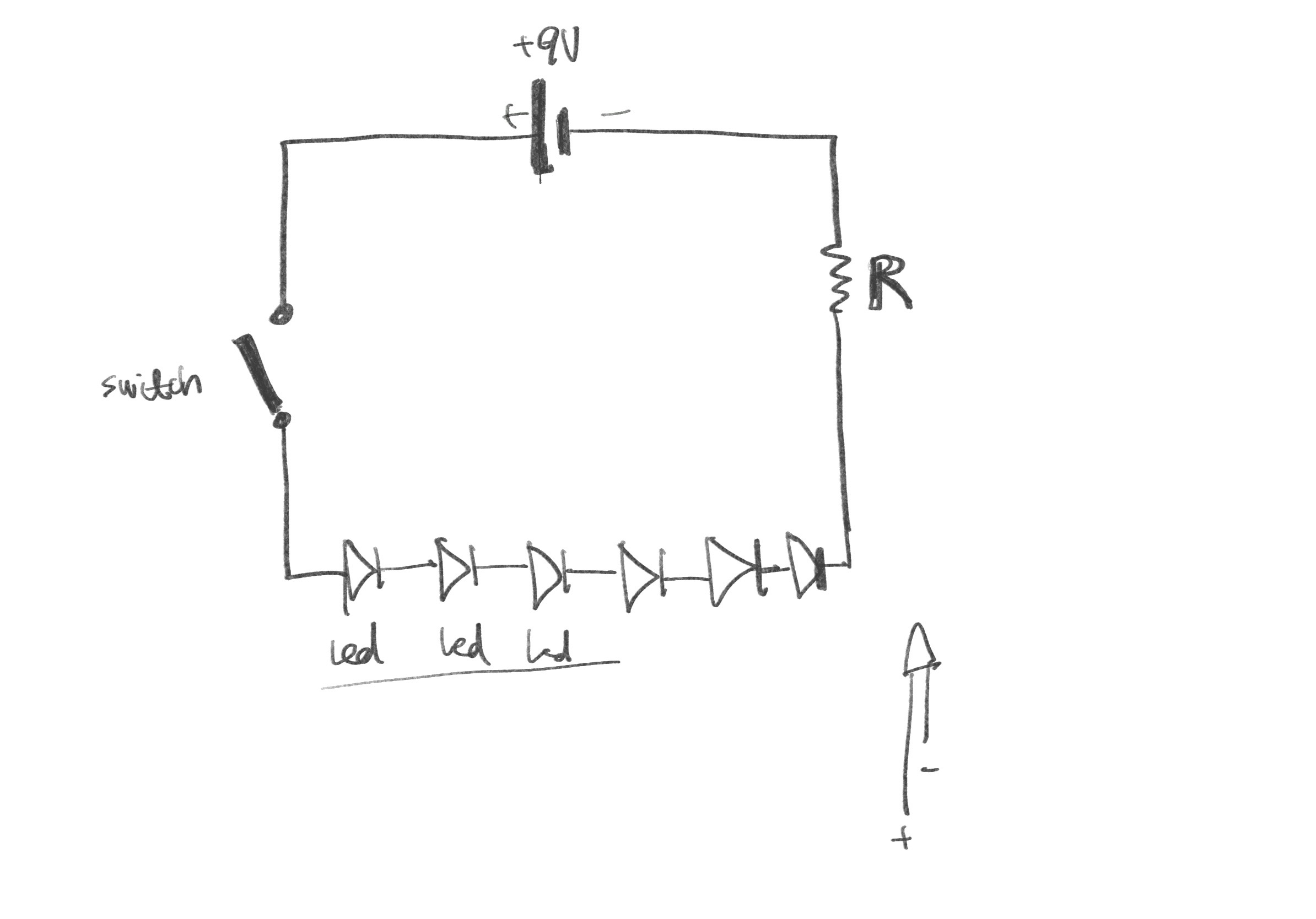
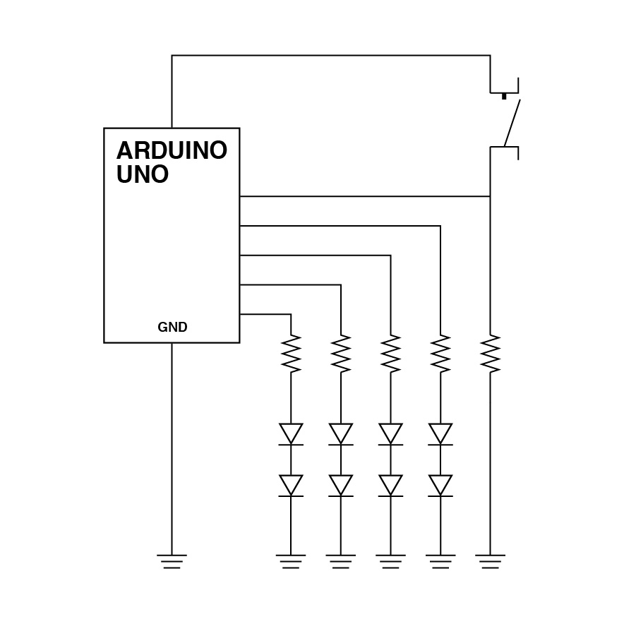
First, we drew a schematic in which 8 LED lights are connected in a series. Following this schematic, we assembled the components. However, the lights did not turn on. We assumed that itthis wasis due to the high voltage that the eight lights were not working.
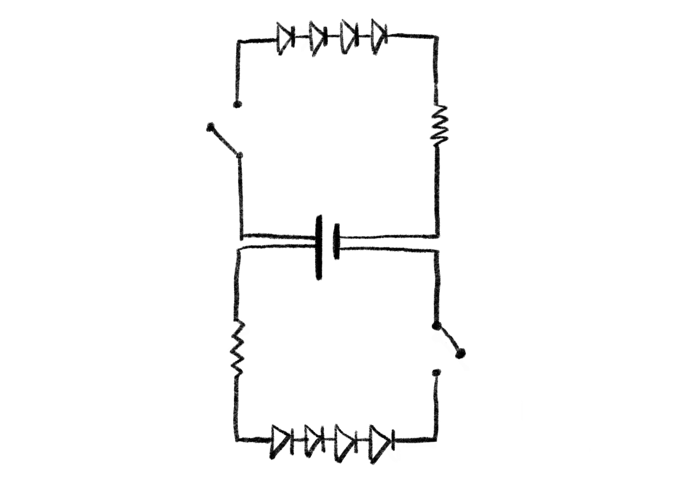
To solve the problem in the first schematic, we tried to divide the 8 LED lights into two sectionsparts of 4 LED lights each and connected them to the 9V battery.
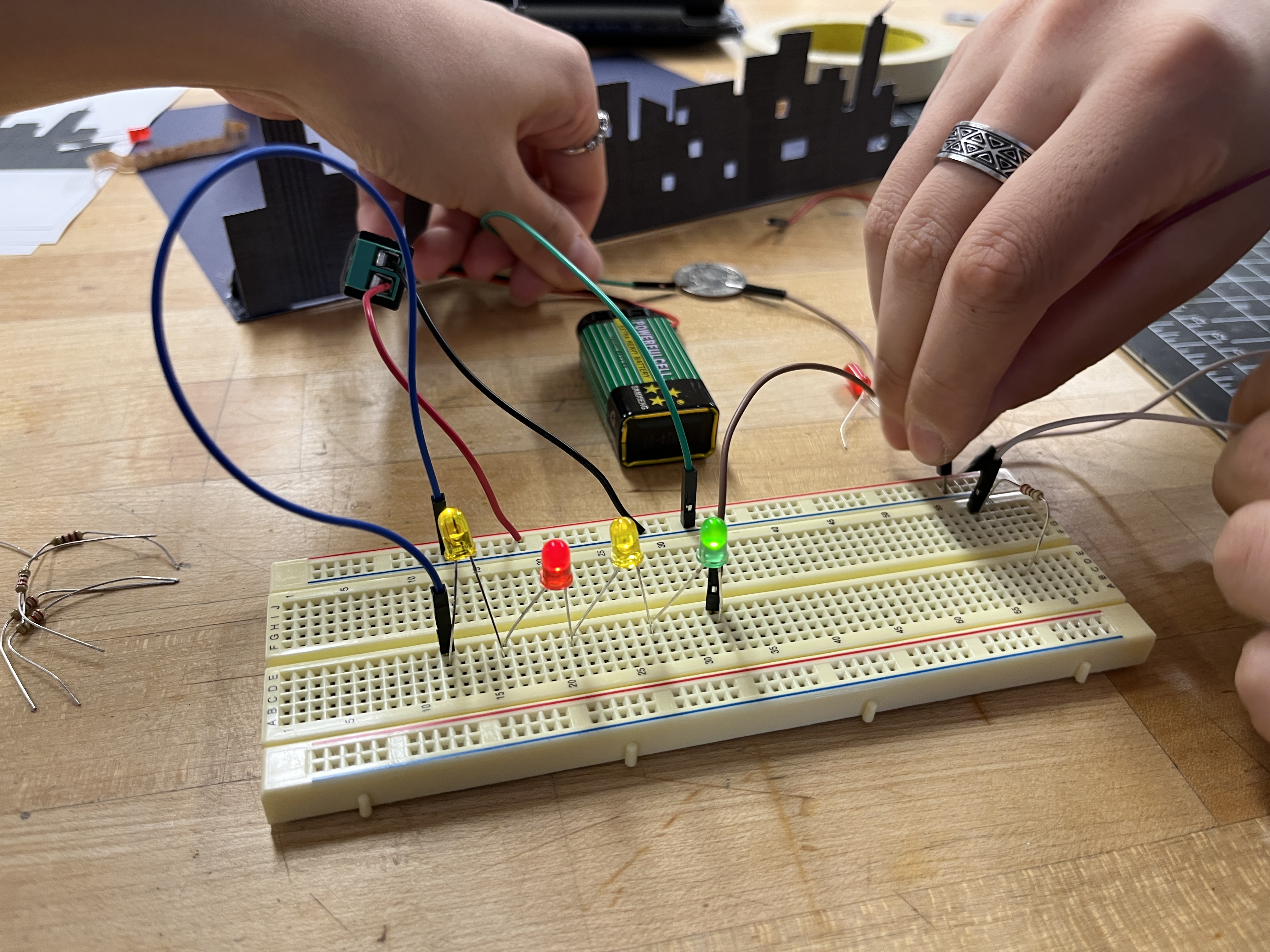
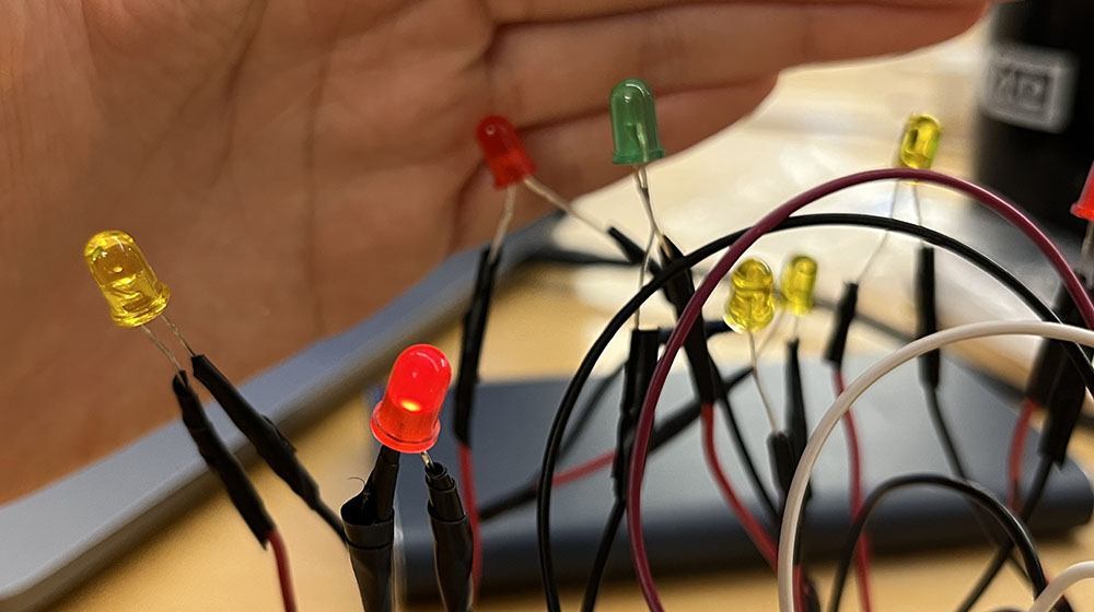
First, we tested our coin switches and made them work with our tools.
Next, we attempted it with a parallel connection instead of a serial connection. We didn’t consider the switch while assembling it. So even though the LED lamps were operating, the link wasn’t suitable for a homemade switch.
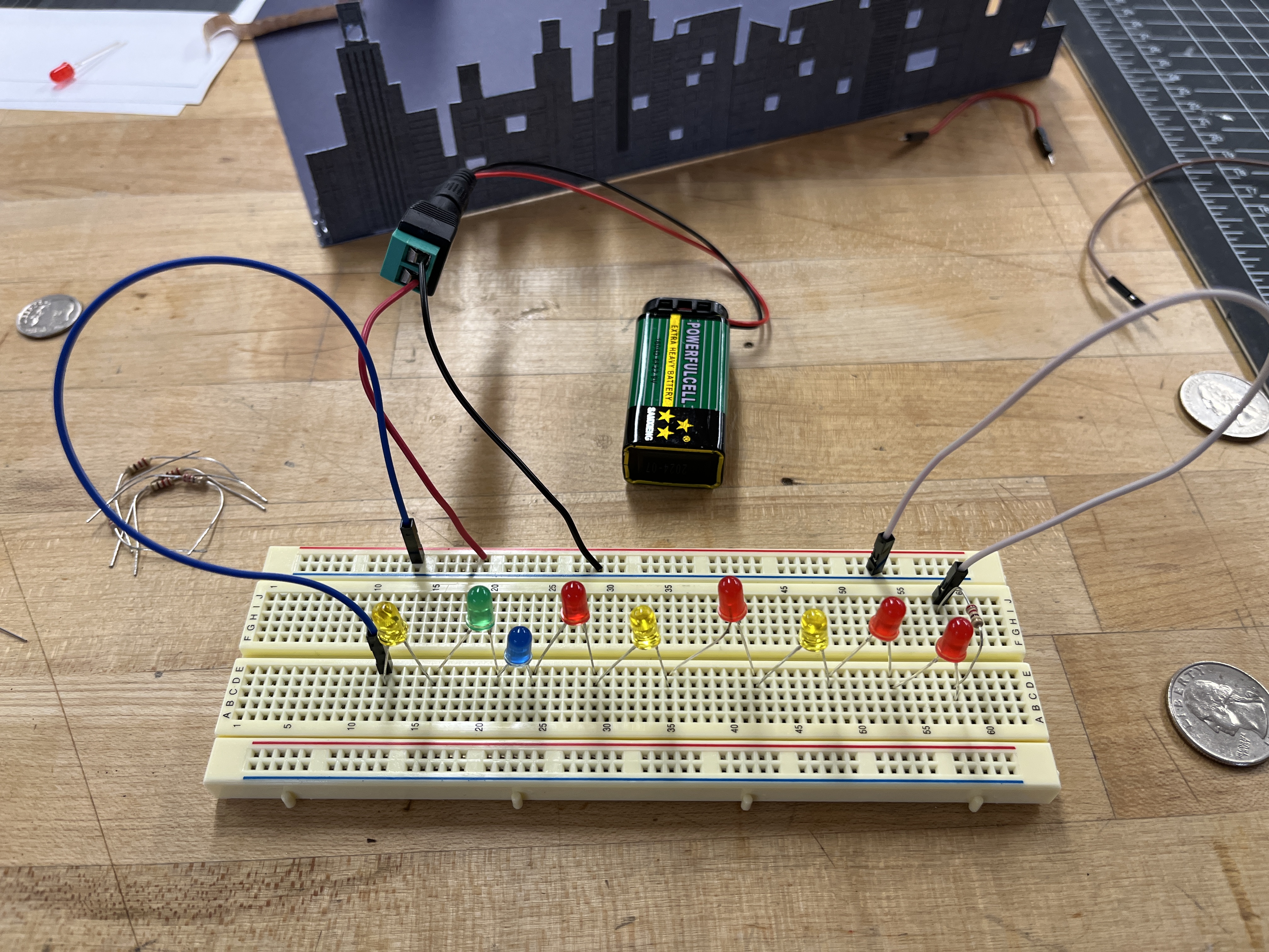
We connected the LED lights incorrectly with regard to regarding the plus(anode) and minus sides(cathode), which resulted in the lights not working. What we first attempted with the LED lights was + - - + + - - + …. . However, we had misunderstood the current flow. Weand fixed the issue by setting upputting the LED lights correctly later on the fourth attempt. Later wWe changed the direction of the LED lights to + - + - + - + - ….
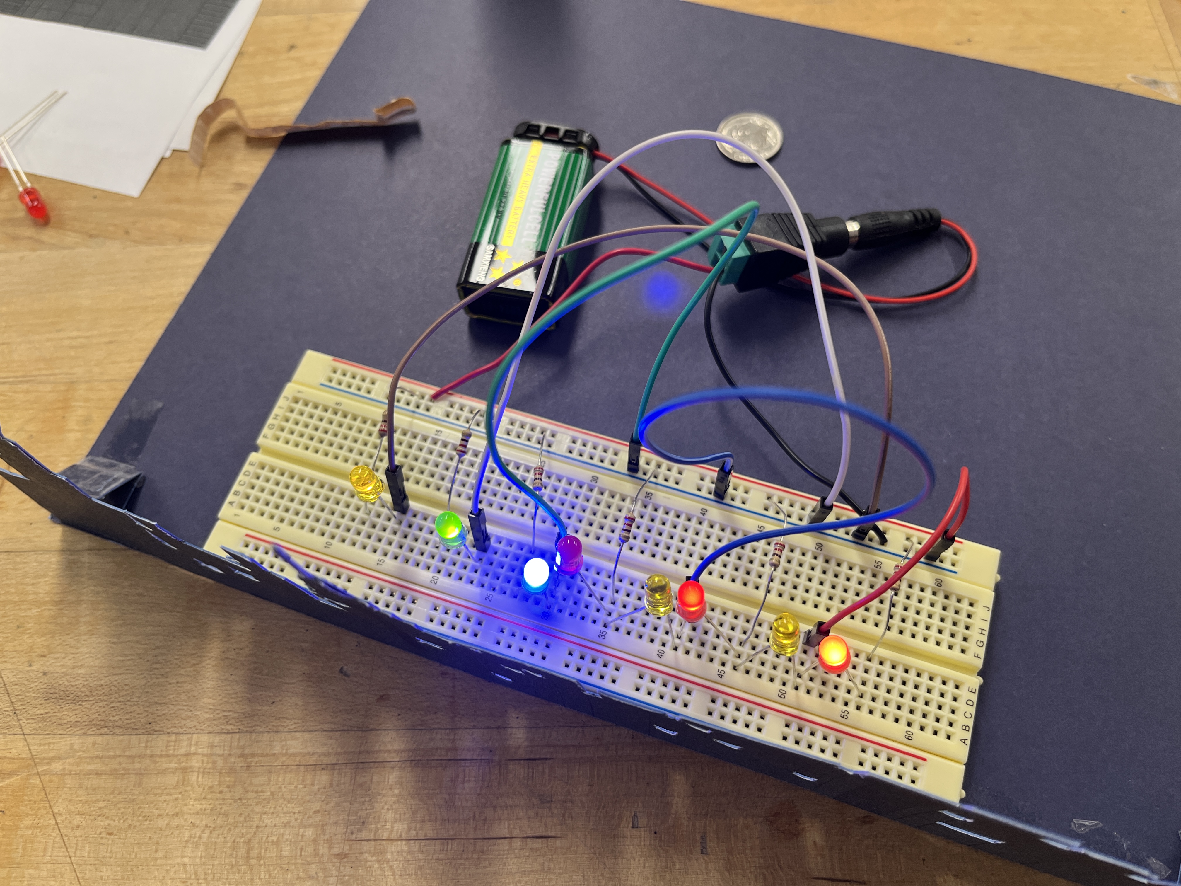
We tried a serial connection, but the power was not strong enough to make more than 4 LED lights work. Out of 8 LED lights in a row, only 4 seemed to be fully working. This is why we came up with a revised schematic system and returned to the combination of parallel connections using two switches. In conclusion, this problem occurred becauseas we didn’t fully understand the structure of the breadboard.
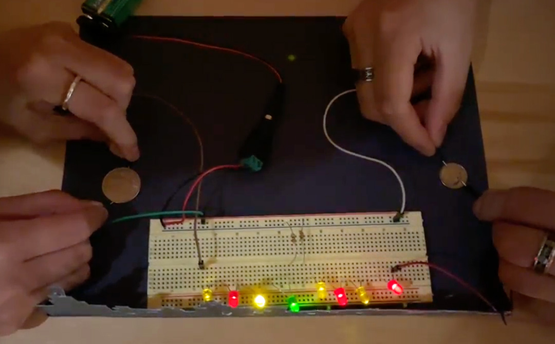
Later we found out it was the issuematter of the direction of the current that made the LED lights not bright enough. Later we found out that the reason the LED lights weren’t bright enough was the issue of the direction of the current. We made two working switches with one battery (power source) by readjusting and organizing the resistors, wires, LED lights, and switches.
The outcome includes two switches operated by positioning the coin, that lighten up the city.
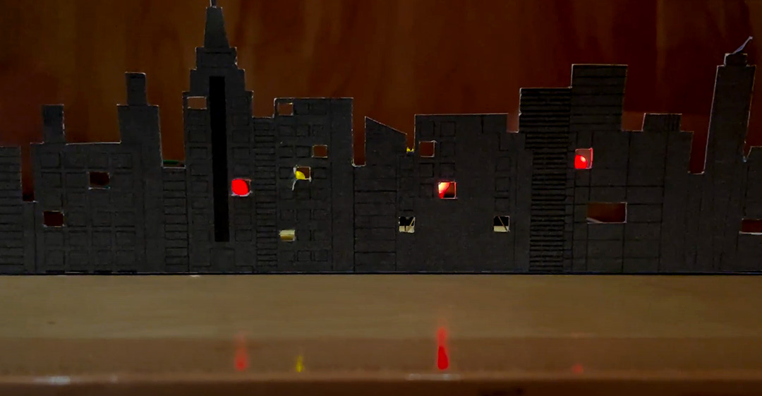
Overall the light was not strong enough to create make the “Manhattan at night” effect we’d imagined. There washad been an issue withof positioning the light with the window of the building to make proper light eliminating effect through the window. It was difficult to position the lights in the windows of the buildings to create the proper effect of light shining through the windows.
We previously created a night view of the Manhattan skyline. To make improvements, we decided to develop the structure design and use code written using Arduino and a micro conductor. This time we wrote code using Arduino and its JS library so that the LED light can be turned on gradually when the button is pressed.
We created a new Manhattan skyline illustration to address the issue of the previous project, dim led lights in a light room. To increase the brightness of the LED lights, we built a box-shaped frame around the city graphic to generate a shadow, which allows the artwork to stay black, making the LED lights look brighter.
The push we used in class only connected current flows when pressed, so we changed it to a sliding switch. The sliding switch is a common representation of “turning the light on.” which is why it was appropriate for this project.
void setup() {
    // initialize digital pin LED_BUILTIN as an output.
    pinMode(1, OUTPUT);
    pinMode(2, OUTPUT);
    pinMode(3, OUTPUT);
    pinMode(4, OUTPUT);
    pinMode(5, OUTPUT); // button
    }
    // the loop function runs over and over again forever
    void loop() {
    // read pushbutton:
        if (digitalRead(5) == HIGH) {
        // if button is pressed:
        digitalWrite(1, HIGH);  // turn on LED1
        delay(300);
        digitalWrite(2, HIGH);
        delay(350);
        digitalWrite(3, HIGH);
        delay(400);
        digitalWrite(4, HIGH);
        delay(450);
        }
        else {
        // if button is not pressed:
        digitalWrite(1, LOW);  // turn off LED1
        digitalWrite(2, LOW);
        digitalWrite(3, LOW);
        digitalWrite(4, LOW);
        }
    }
When we first installed the switch to the Arduino board, we weren’t fully aware of its function. We did not turn on the switch, and it stopped delivering the power to the Arduino board and sending information to the MacBook.Besides the recognition issue, the code was well compiled and uploaded to the board during the testing stage.
Only one light turned on: We didn’t unify the register, so only one LED light using the right resistor worked. After finding this issue, we changed all the resisters to 330Ω resisters.
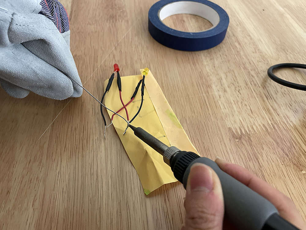
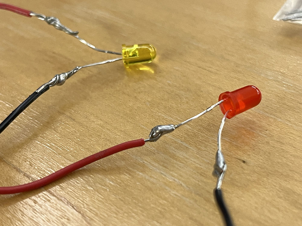
There was a problem with the electricity not flowing through correctly to the LED lights when we wired them together using electrical tape. Because they were not soldered properly on the first attempt, they weren’t fully connected.
After learning about how to use a buzzer and a photoresistor in class, we are asked to create a simple application with either sound or movement as an output.
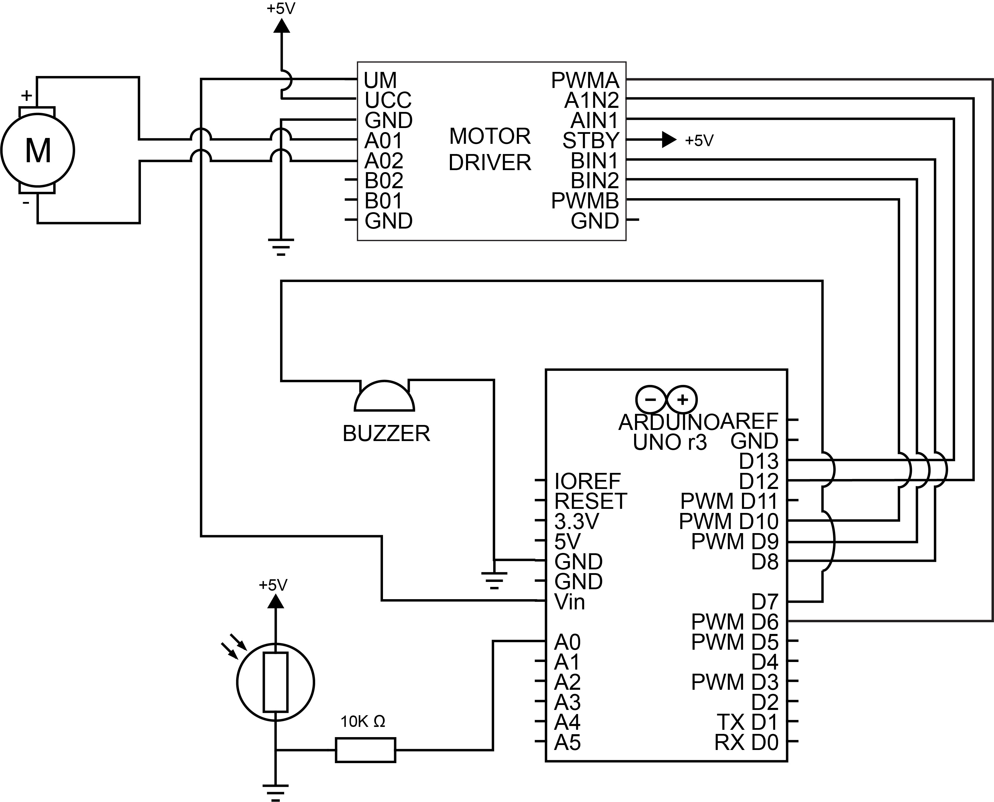
The doomsday clock shows the time left till doom. But with our action - covering the small piece of nature (with photoresistor inside) with our hand - it can stop the clock ticking and eventually stop doomsday. For this ideation, we decided to use a motor, buzzer, and photoresistor.
Our attempt on connecting the servo motor and photoresistor was successful. However, we couldn’t get the 360-degree turn using this motor, so we changed to another motor.
When we tried to run the motor with the switch and it turned out successful. However, the code we applied only worked when we put speed on the terminal. We later changed it so that it works purely with the switch.
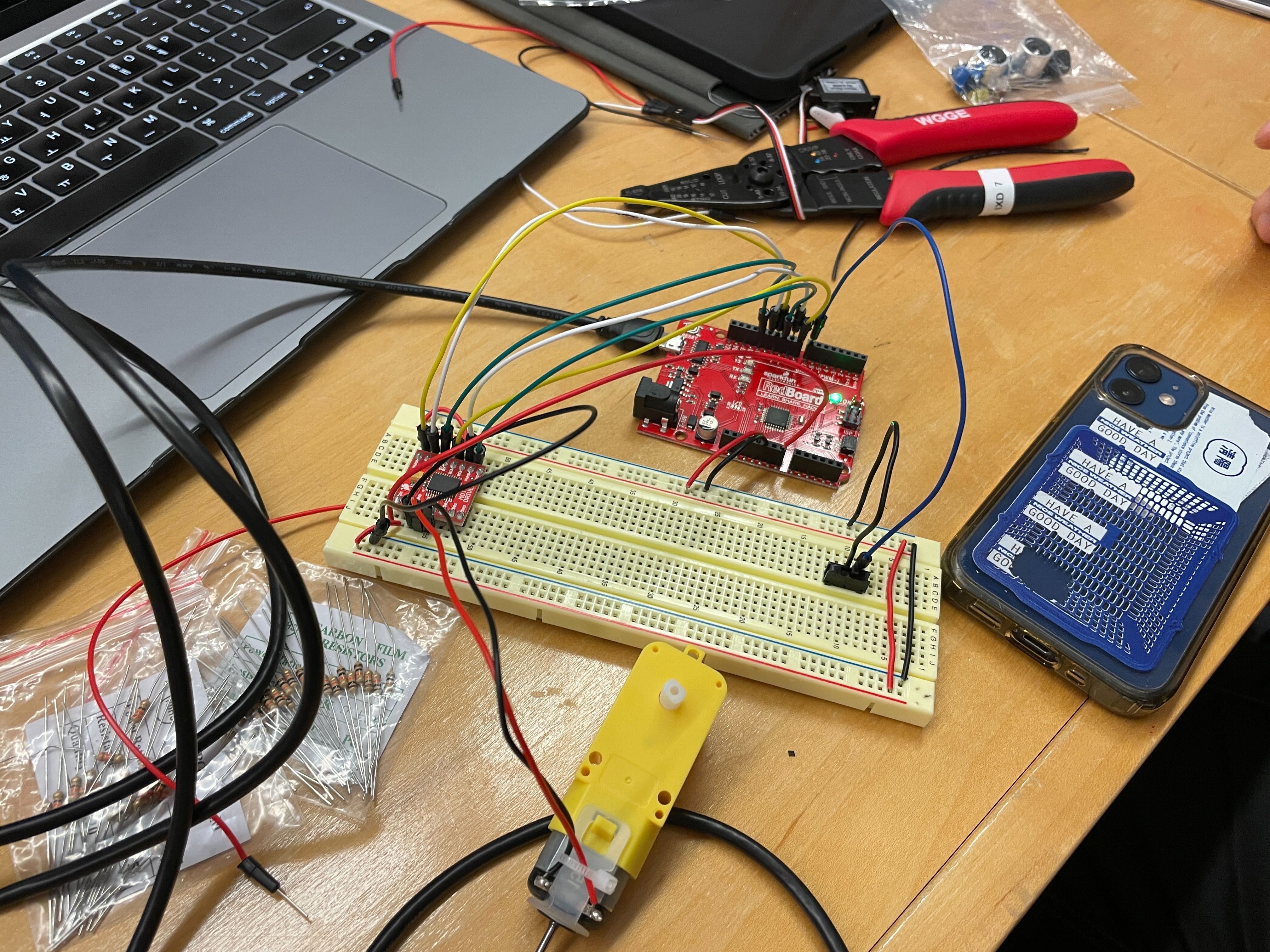
We connected the motor to the light sensor with the revised code, and we were able to make the speed of the motor sensitive to the light. When we covered it with our hands, the motor slowed down and eventually stopped. Now it was time to connect.
The buzzer was later added to create a sound similar to a clock, but the motor was not working when the buzzer was connected.
It turned out the TONE function interferes with specific pins - 3 and 11, so we changed the pin number 11 to 6. After the update on the code as well, both motor and buzzer started working. After we succeed in this, we moved on to creating a prototype.
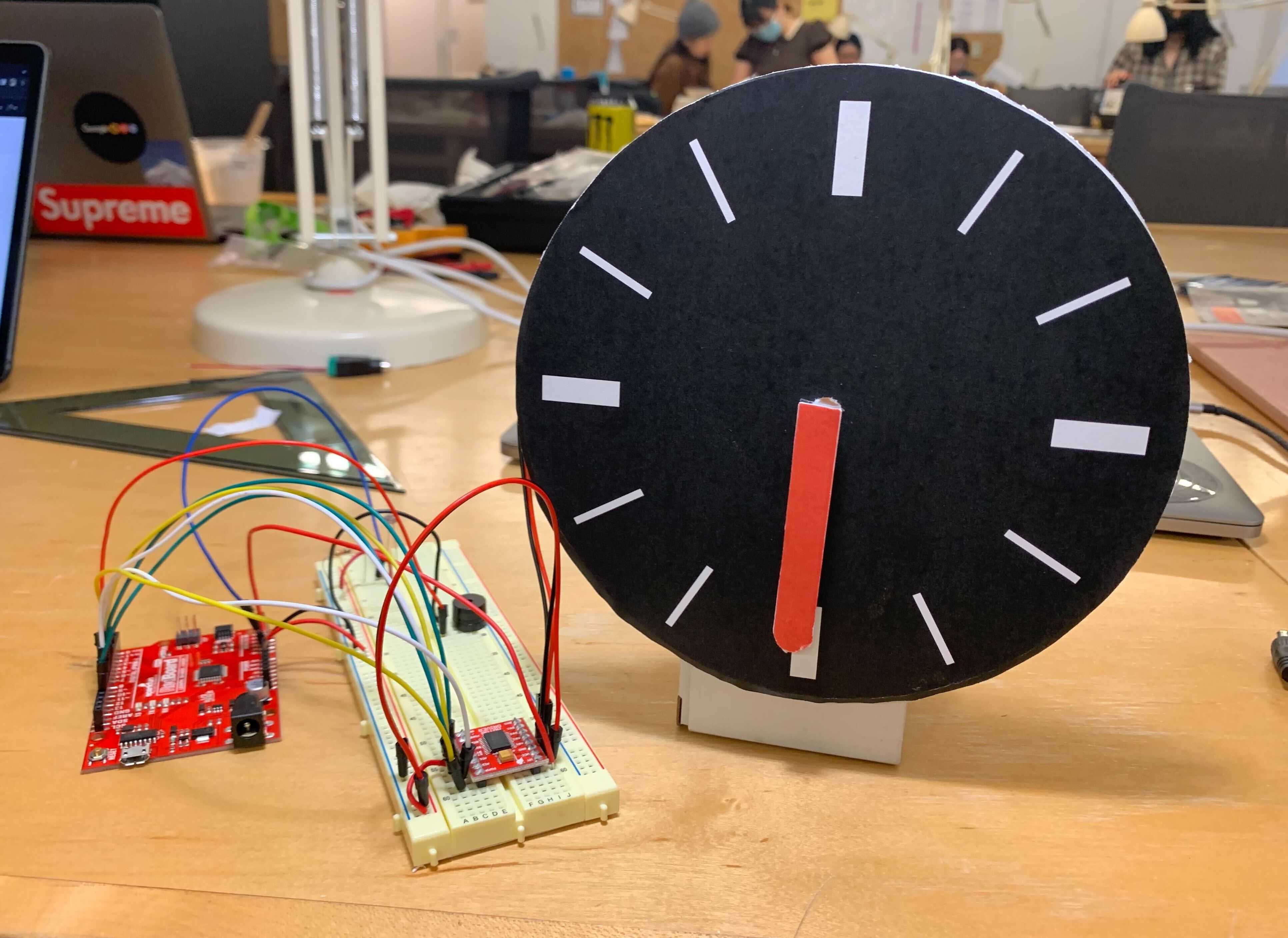
We ensured that the photoresistor was in an accessible position for the user to cover it and make the circuit work.
const int AIN1 = 13;
const int AIN2 = 12;
const int PWMA = 6;

int motorSpeed = 100;
const int buzzerPin = 7;

void setup() {
    pinMode(AIN1, OUTPUT);
    pinMode(AIN2, OUTPUT);
    pinMode(PWMA, OUTPUT);

    Serial.begin(9600);
    pinMode(buzzerPin, OUTPUT);
}

void loop() {

    int brightness = analogRead(A0);
    Serial.println(brightness);

    float motorSpeed = map(brightness, 300, 900, 10, 50);
    float frequency = map(brightness, 300, 900, 100, 2000);
    int speed = map(brightness, 300,900,3000,100);
    if (brightness > 300) {
        noTone(buzzerPin);
    }
    tone(buzzerPin,frequency, 10);
    delay(speed);

    spinMotor(motorSpeed);
}

void spinMotor(int motorSpeed)
{
    if (motorSpeed > 0)
    {
    digitalWrite(AIN1, HIGH);
    digitalWrite(AIN2, LOW);
    }
    else if (motorSpeed < 0)
    {
    digitalWrite(AIN1, LOW);
    digitalWrite(AIN2, HIGH);
    }
    else
    {
    digitalWrite(AIN1, LOW);
    digitalWrite(AIN2, LOW);
    }
    analogWrite(PWMA, abs(motorSpeed));
}
When we were testing the prototype, there was a slight delay in restarting both the buzzer and motor, which we have not figured out yet. When we increase the frequency of the buzzer, the delay disappeared. We thought that it has something to do with speed and frequency.
When trying to debug, we first examined all the connections on the breadboard and then the code. After we found no apparent errors, we thought that it was because the power supply was not strong enough. However, we tested a few methods to increase the power and it was still not working. Eventually, we found out through Google that only certain ports can be used for the motor. Our conclusion is that it’s helpful to switch perspectives when one debugging direction is not working out.

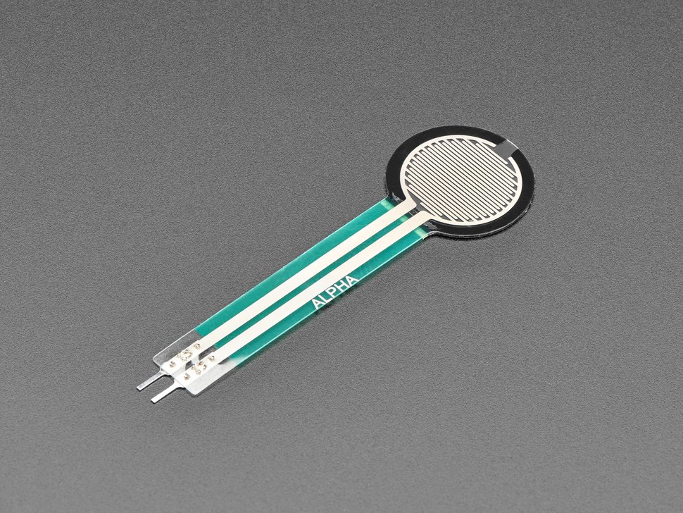
FSRs are sensors that allow you to detect physical pressure, squeezing and weight. They are simple to use and low cost. The FSR is made of 2 layers separated by a spacer. The more one presses, the more of those Active Element dots touch the semiconductor and that makes the resistance go down.
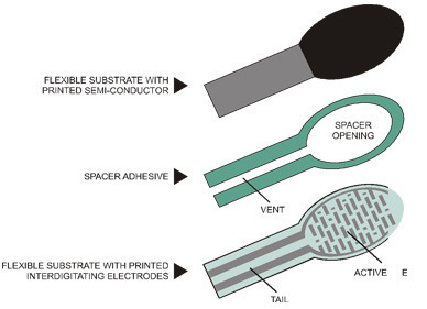
FSRs are basically a resistor that changes its resistive value (in ohms Ω) depending on how much it is pressed. These sensors are fairly low cost, and easy to use but they're rarely accurate. When you use FSRs you should only expect to get ranges of response.
var five = require("johnny-five"),
fsr, led;

(new five.Board()).on("ready", function() {

// Create a new `fsr` hardware instance.
fsr = new five.Sensor({
    pin: "A0",
    freq: 25
});

led = new five.Led(9);

// Scale the sensor's value to the LED's brightness range
fsr.scale([0, 255]).on("data", function() {

    // set the led's brightness based on force
    // applied to force sensitive resistor

    led.brightness(this.scaled);
});
});
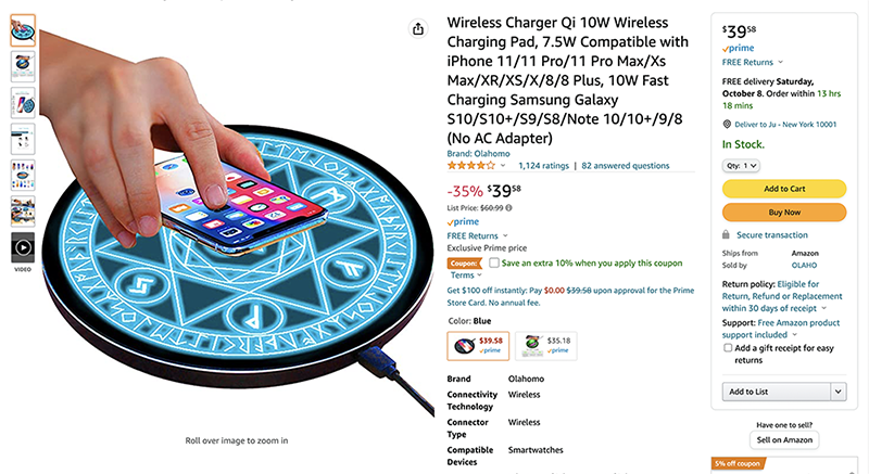
This magic circle charger is still currently in my Amazon shopping list. But what if I make one for myself to feel like anime magic girl?
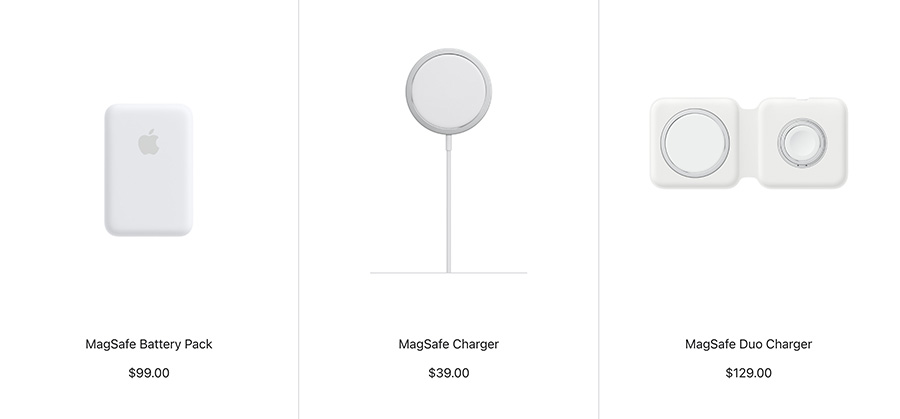
Most wireless chargers use magnetic induction and magnetic resonance. They offer the promise of being able to place a device on a surface and have it charge automatically—no fiddling with cables required.
Wireless charging isn’t truly wireless, of course. Your phone, smart watch, tablet, wireless headphones, or other device doesn’t need to be plugged into the charger with a wire, but the wireless charger itself still has to be plugged into a wall outlet to function.
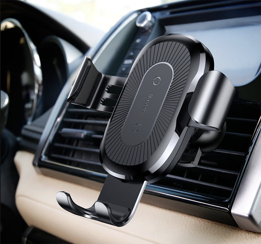
Despite it's downside, it still can be useful in specific cases.
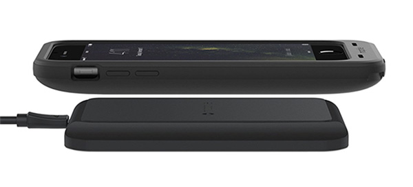
Wireless chargers typically use magnetic induction. The short explanation is that they use magnetism to transmit energy. First, you place the device–like a smartphone—on the wireless charger. The current coming from the wall power outlet moves through the wire in the wireless charger, creating a magnetic field. The magnetic field creates a current in the coil inside the device sitting on the wireless charger. This magnetic energy is converted to electrical energy, which is used to charge the battery. Devices must have the appropriate hardware in them to support wireless charging—a device without the necessary coil can’t charge wirelessly.
Does anyone remember the excitement of sitting in front of the TV and waiting for our favorite show to start? Does anyone remember collecting branches and rags to play as the character that we admired as kids? This project is inspired by that inner child of ours. Time will pass, but emotions stay. Looking back, we might laugh at our silliness, yet we will always feel reminiscent about how simple things could bring us so much happiness.
With those thoughts in mind, we drew inspiration from one of our childhood favorite shows: Card-captor Sakura. By mimicking the signature Sakura gesture, we want to create an interactive project that represents the magic-wand experience to bring our audience a moment of happiness and amazement.
The idea is that when the user waves the magic wand, magical effects will happen on the screen and surprise the users.
The input will be the pressure sensor because the user will use the magic wand to press the sensor and trigger the animation. The output will be a p5.js animation on a laptop screen because this results from the interaction (what the users will see).
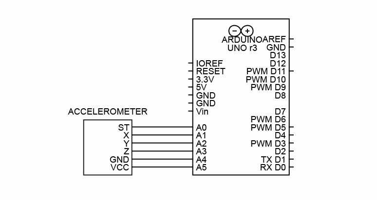
We decided to change the FSR sensor to an accelerometer that can detect x,y,z axis in space. Thus, the input will be the accelerometer value, and the output will be the moving 3D graphic on p5.js.
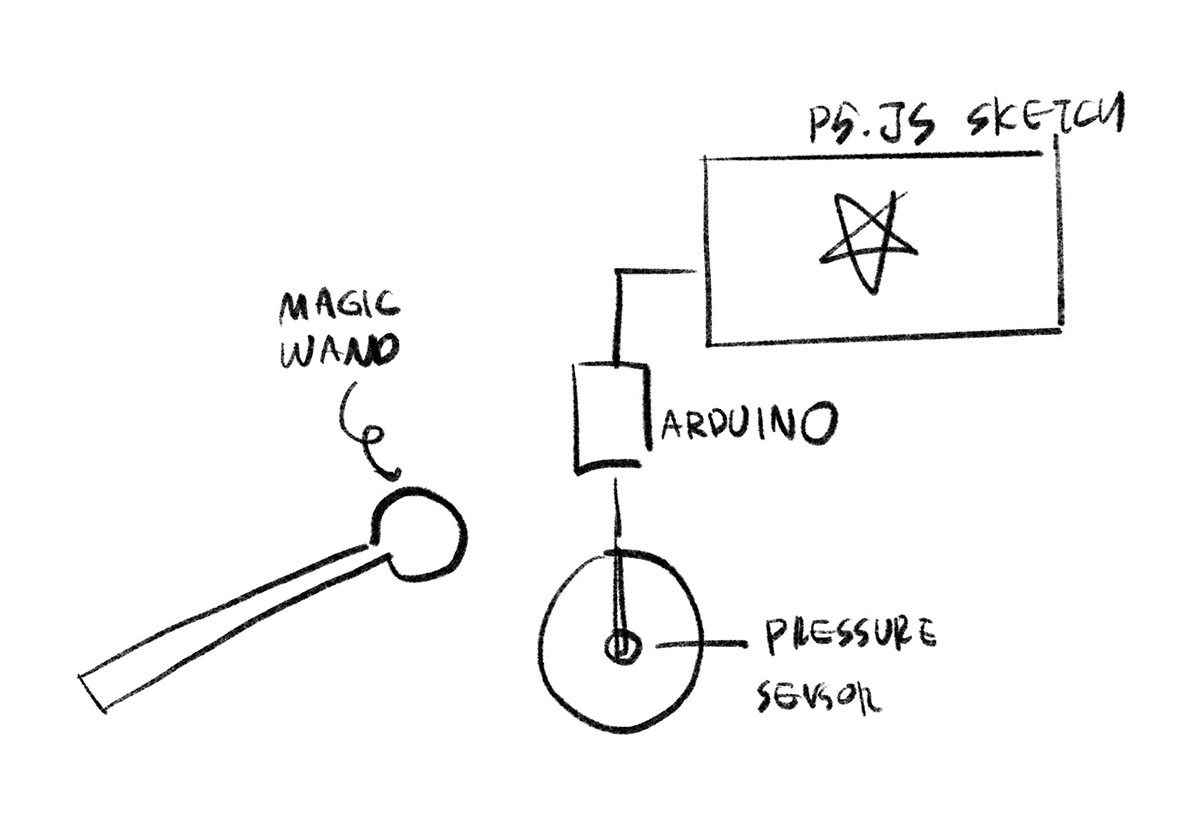
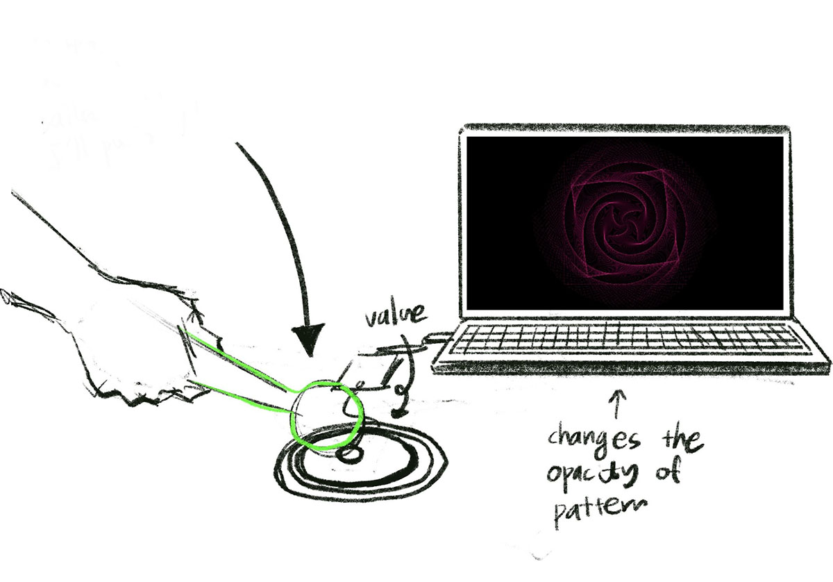


When the participant hit the wand and triggers the pressure sensor, it shows the ‘magic circle’ on the screen using p5.js. The magic circle can be created using loop function, and the sensor can trigger the opacity.
FSRs are sensors that allow you to detect physical pressure, squeezing, and weight. They are simple to use and low-cost. The FSR is made of 2 layers separated by a spacer. The more one presses, the more of those Active Element dots touch the semiconductor and that makes the resistance go down.
FSRs are basically resistors that change their resistive value (in ohms Ω) depending on how much they are pressed. These sensors are fairly low-cost and easy to use but rarely accurate. When you use FSRs, you should only expect to get a range of responses.
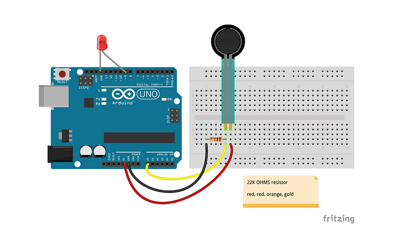
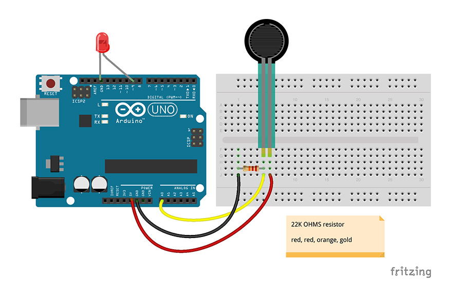
We tested with a pressure sensor to see whether its data value could be seen on the p5.js screen. The initial test was successful, and our next stage would be implementing physical objects (sensor, wand) and animation for p5.js
After the class, we decided to use a sensor that can actually detect the x,y,z axis that can be attached to the wand itself. We decided not to use the pressure sensor, but instead figured out what other sensor we could use.
We attempted to use the Arduino Nano, but it wasn’t receiving any variables from the sensor, and the Arduino program had trouble recognizing the board. After several tests, we moved to another sensor.
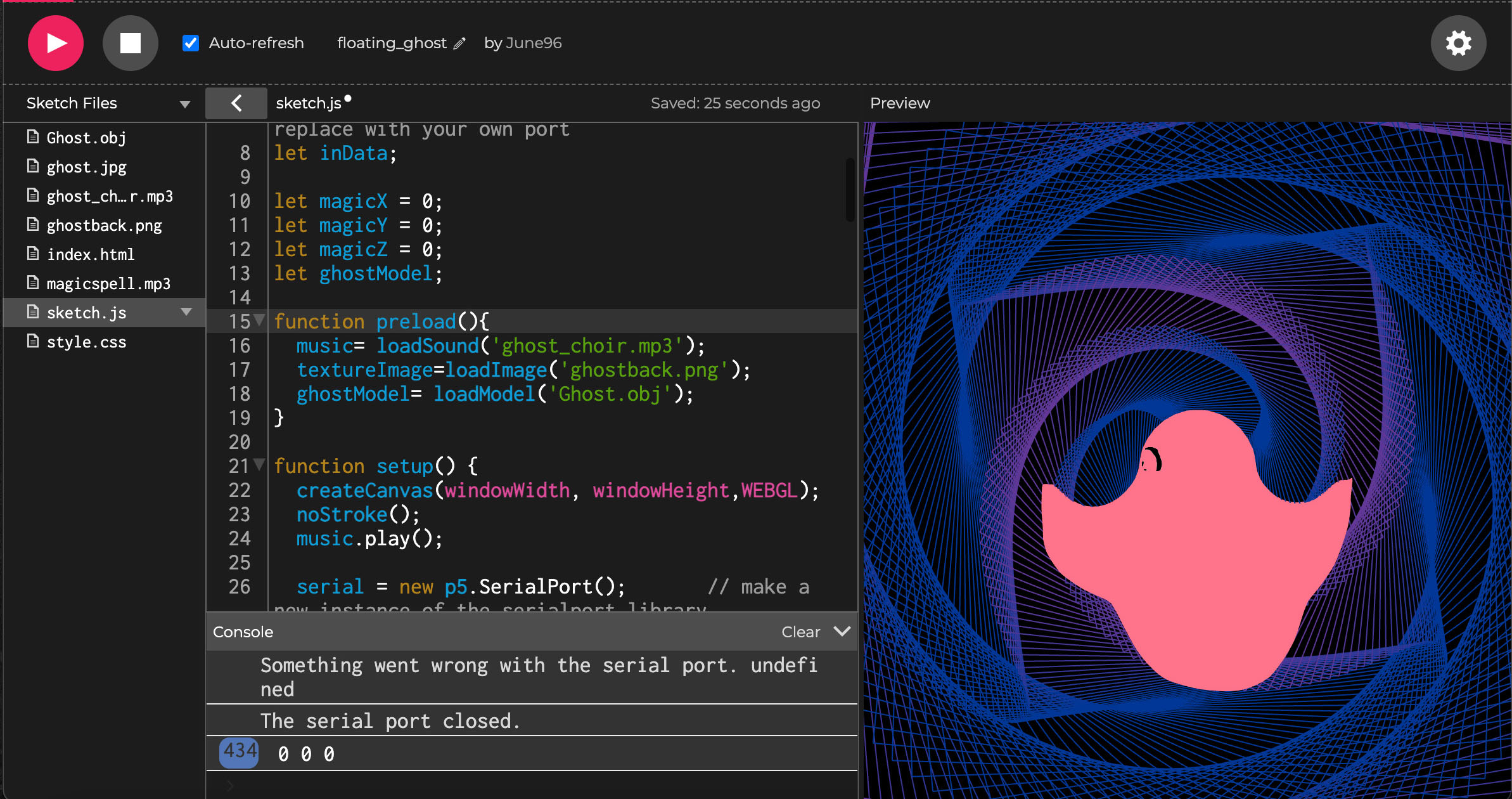
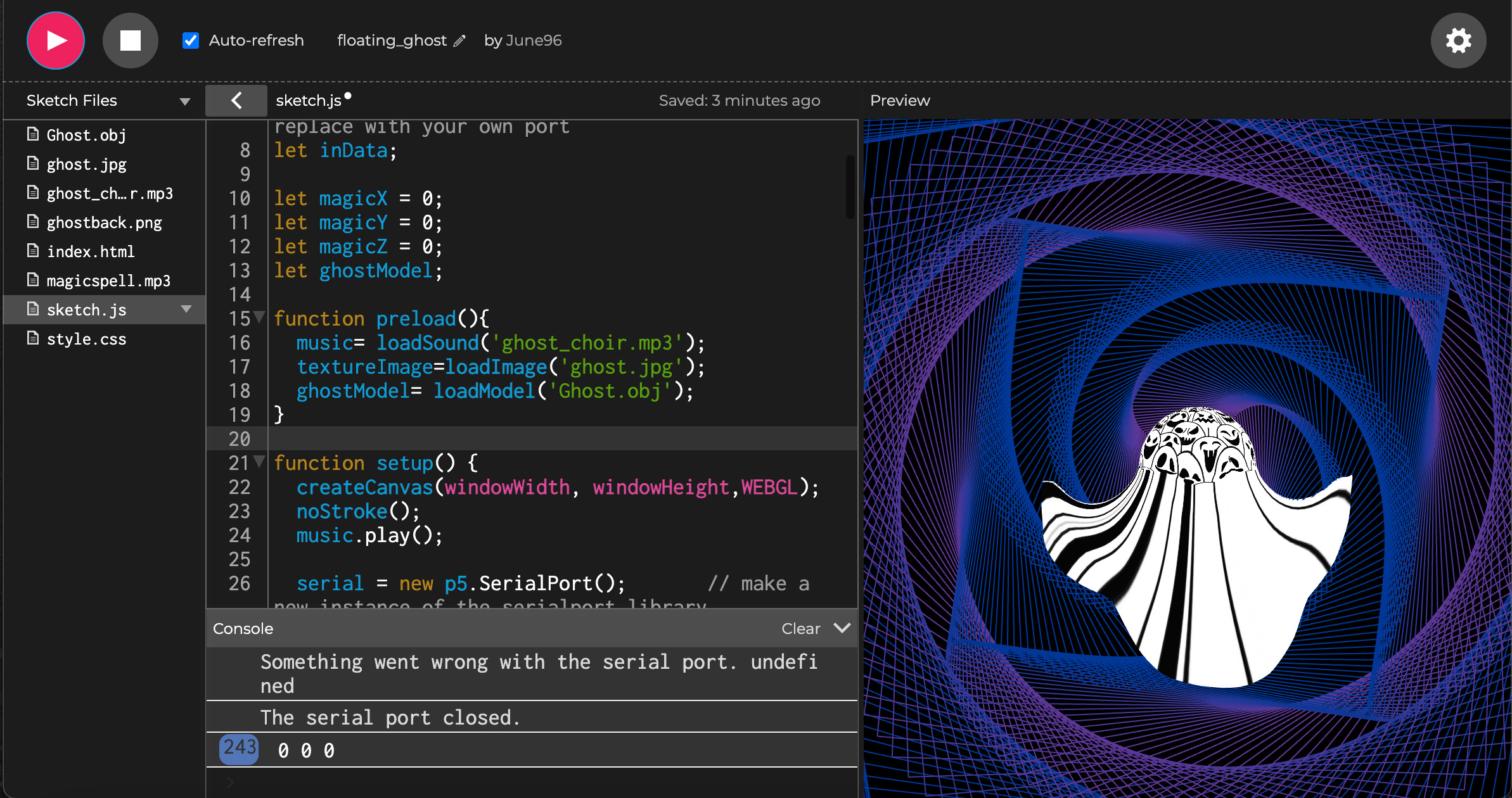
We were able to use an accelerometer and succeeded in getting x,y, and z axis variables from the Arduino program. For the p5.js output, we added for-loop-animation on the background and a 3D object that can be adjusted by the sensor. After a few tests, we succeeded in making p5.js output but couldn’t figure out how to connect them with sensor input.
For some reason, handshake wasn’t working for our code (the accelerometer was not sending values to p5). It worked after we removed the handshake part in Arduino and p5.
Our code was supposed to send three values to p5, but we didn’t fully understand the process and kept trying to send only one value. This was a prior failure while connecting the Arduino and p5.
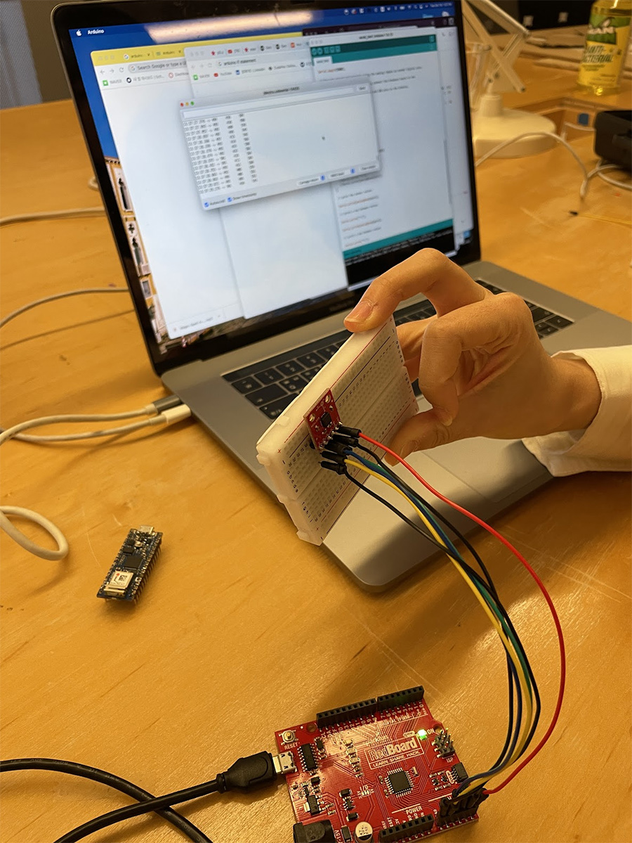
With Eric and Viola’s help, we made a 3D object interact with the accelerometer. After setting up the accelerometer, uploading Arduino code, and setting up p5.js, we tested whether it works.
    const int groundpin = 18;             // analog input pin 4 -- ground

    const int powerpin = 19;              // analog input pin 5 -- voltage

    const int xpin = A3;                  // x-axis of the accelerometer

    const int ypin = A2;                  // y-axis

    const int zpin = A1;

    int x;
    int y;
    int z;

    int incomingByte;

    void setup() {

        Serial.begin(9600);

        pinMode(groundpin, OUTPUT);
        pinMode(powerpin, OUTPUT);
        digitalWrite(groundpin, LOW);
        digitalWrite(powerpin, HIGH);

    }

    void loop() {
        x = analogRead(xpin);
        y = analogRead(ypin);
        z = analogRead(zpin);

        incomingByte = Serial.read();

        Serial.print(analogRead(xpin));
        Serial.print(", ");
        Serial.print(analogRead(ypin));
        Serial.print(", ");
        Serial.println(analogRead(zpin));

        delay(100);
    }
                        var widthSplit
    var heightSplit
    var music;
    let serial;
    let portName = '/dev/tty.usbserial-1130';
    let inData;

    let magicX = 0;
    let magicY = 0;
    let magicZ = 0;
    let ghostModel;

    function preload(){
        music= loadSound('ghost_choir.mp3');
        textureImage=loadImage('ghost.jpg');
        ghostModel= loadModel('Ghost.obj');
    }

    function setup() {
        createCanvas(windowWidth, windowHeight,WEBGL);
        noStroke();
        music.play();

        serial = new p5.SerialPort();       // make a new instance of the serialport library
        serial.on('list', printList);  // callback to list all the ports
        serial.on('connected', serverConnected); // callback for connecting to server
        serial.on('open', portOpen);        // callback to check port opening
        serial.on('data', serialEvent);     // callback for when new data arrives
        serial.on('error', serialError);    // callback for errors
        serial.on('close', portClose);      // callback for the port closing

        serial.list();                      // list the serial ports
        serial.open(portName);

    }

    function draw() {
        background(0);
        stroke(255)

        rectMove()
        angleMode(DEGREES);
        rectMode(CENTER);


        translate(magicX,magicY,magicZ);
        console.log(magicX, magicY, magicZ);
        scale(50)
        rotate(180)
        noStroke();
        //
        texture(textureImage);
        model(ghostModel);
        //sphere(100);
    }

    function rectMove(){
        noFill()
        //Attempt on centering
        widthSplit = width/64
        heightSplit = height/64
        translate(widthSplit, heightSplit)
        for (var i = 0; i < 200; i++ ){
        push()
        rotate(sin(frameCount + i*2)* 100)
        myColour = (sin(frameCount + i*3)* 100)
        stroke(myColour,55,150,50);
        rect (0,0,600 - i*3,600 - i*3);
        // rect (500,500,600 + i*3,600 + i*3);
        pop();
        }
    }


    // Serial
    // get the list of ports:
    function printList(portList) {
        // portList is an array of serial port names
        for (var i = 0; i < portList.length; i++) {
        // Display the list the console:
        console.log("port " + i + ": " + portList[i]);
        }
    }

    function serverConnected() {
        console.log('connected to server.');
    }

    function portOpen() {
        console.log('the serial port opened.')
    }

    function serialEvent() {
        // read a String from serial port
        // until you get carriage return and newline:
        let inString = serial.readStringUntil('\r\n');  //store in a variable
        //check to see that there's actually a string:
        if (inString.length > 0){
        // if (inString !== 'hello') {
            let inputs = split(inString, ',');   // split the string on the commas, put into an array
            if (inputs.length > 2) {       // if there are two or more elements
            magicX = inputs[0];
            magicY = inputs[1];
            magicZ = inputs[2];
            // magic readings
            magicX = map(magicX, 400, 700, -200, 200);
            magicY = map(magicY, 400, 700, -200, 200);
            magicZ = map(magicZ, 400, 700, -200, 200);
            }
        }
        // }
        // send a byte to ask for more data ("call and response"):
        // serial.write("A");
    }

    function serialError(err) {
        console.log('Something went wrong with the serial port. ' + err);
    }

    function portClose() {
        console.log('The serial port closed.');
    }
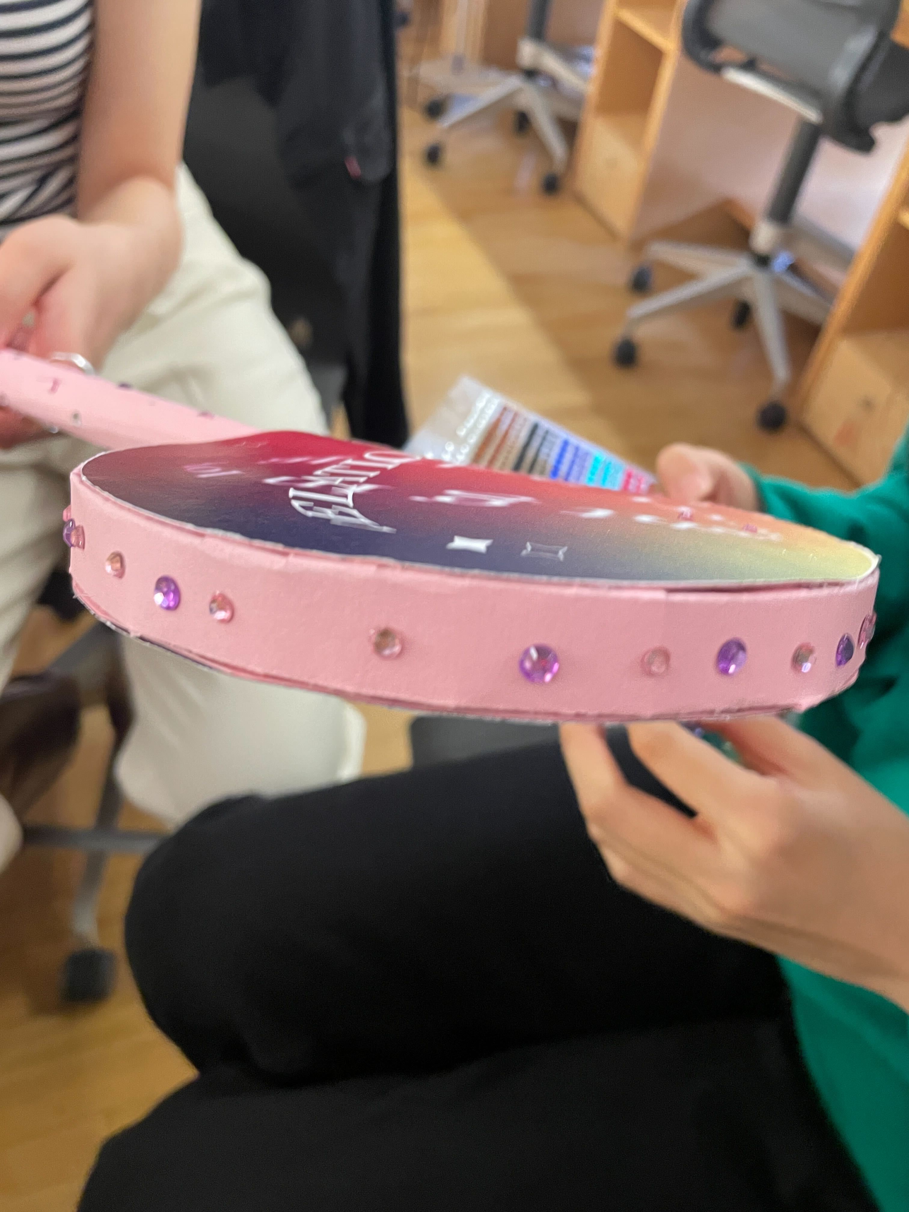
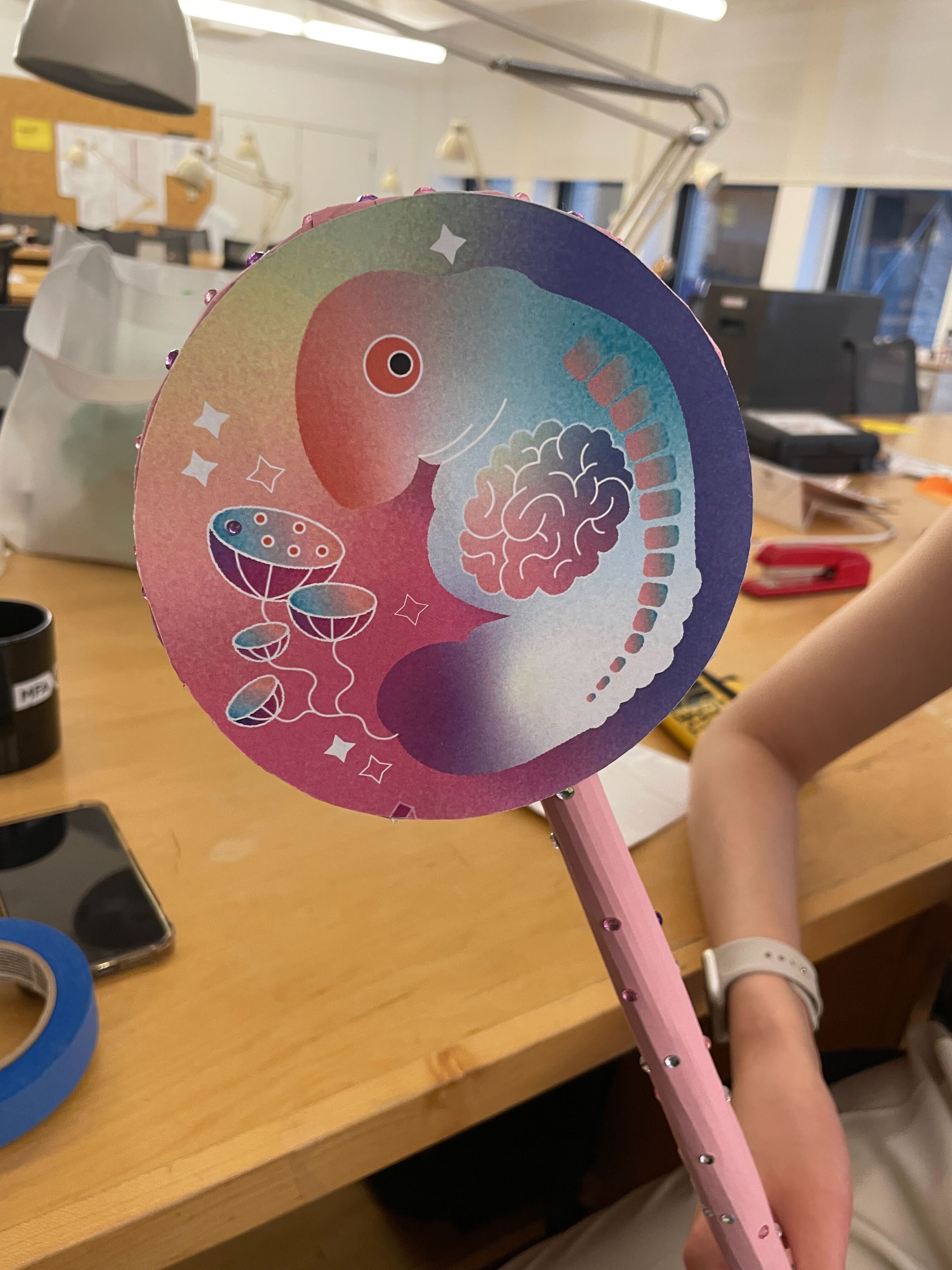
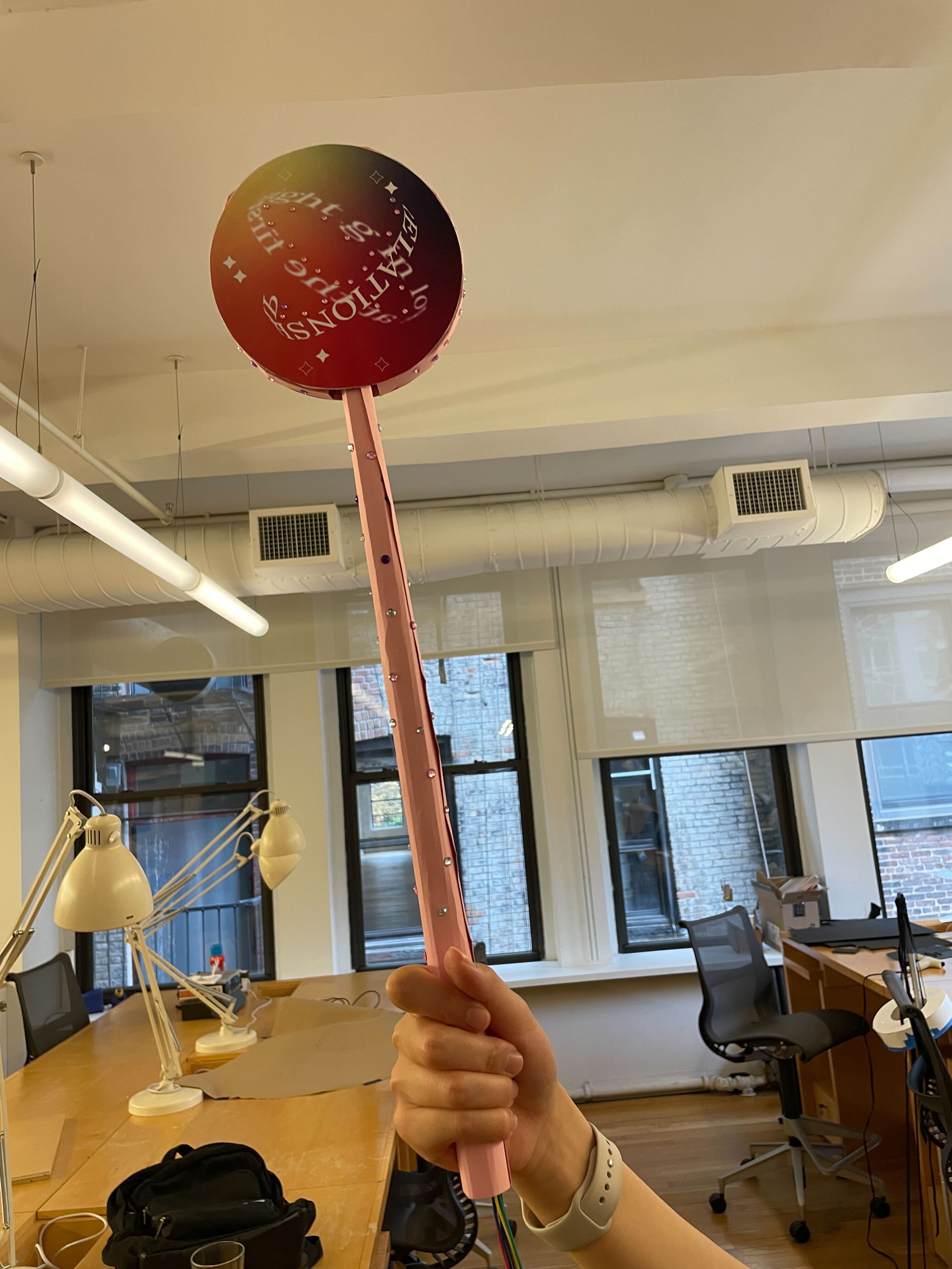
We wanted to make our own wand and went to Michaels’ + Blick Art Material. We purchased a wooden dowel, colored paper, and decorations. We went to the woodshop and used a miter saw to cut the dowel in half. We also created our own magical illustrations and used it as the head part of the wand.
Playing with sensor was very fun. When one sensor didn’t work out, we were quick to seek an alternative solution.
First, we started by connecting 2D-based p5. animation with a pressure sensor to space-responsive 3D p5 work. We succeeded in making the 3D object responsive to physical movement. However, it was not moving as smoothly as we wanted.
In the future, we would like to find out what’s causing the lag, and make 3D object show a smooth movement with clear visual presentation.
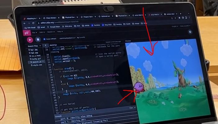
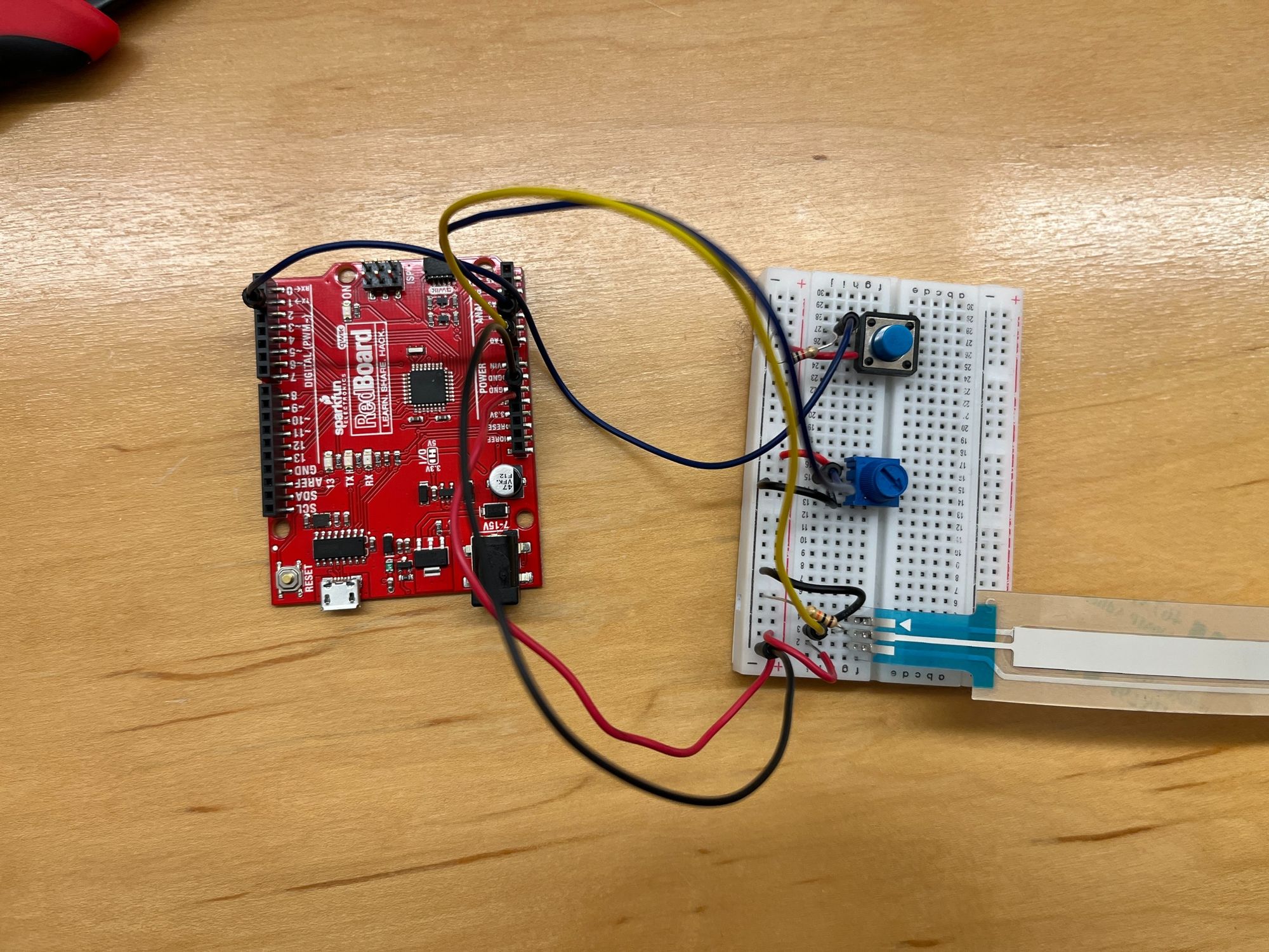
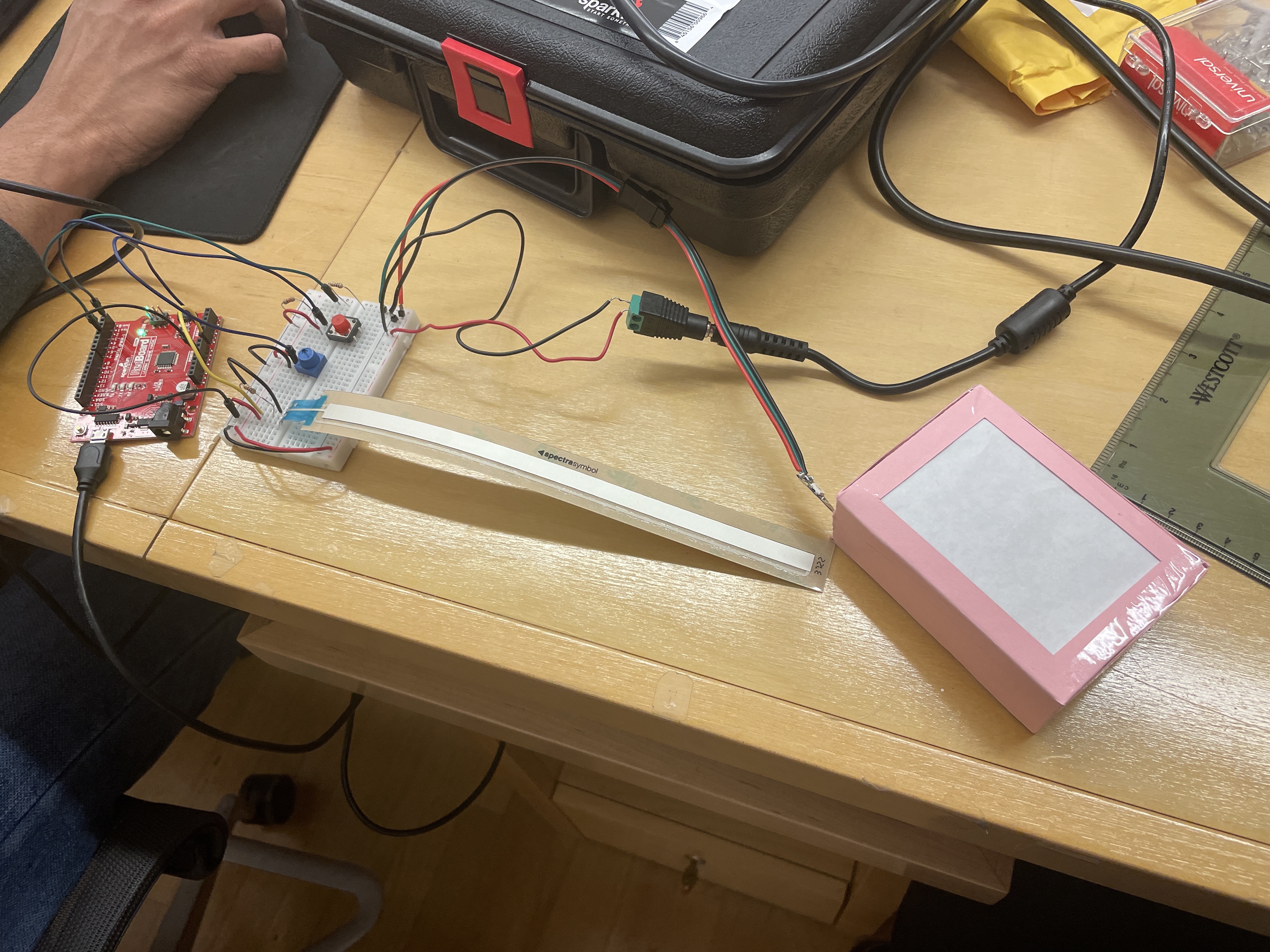
To utilize Arduino for replacing 3 mouse functions and displaying the result via p5.js. We used the translate function(axis x, axis y) and the left click of a mouse as the 3 functions for this project. The potentiometer strip controls the axis x, the potentiometer controls y, and the push button works like a mouse click.
We used a Linear soft Potentiometer strip, Potentiometer, and a button for achieving the goal.
Initially, we used handshaking examples from the lab class and updated both Arduino and p5.js code to be able to get three valuables from three sensors. However, p5 was not receiving the values from Arduino.
Serial.print(sensorVal1); // potentiometer strip
Serial.print(",");
Serial.println(sensorVal2); // potentiometer
Serial.print(",");
Serial.println(sensorVal3); // push button
// Serial Print:
// value1, value2,
// value3
The cause was the println() function which printed it to next line, so we modified it to print();
Serial.print(sensorVal1); // potentiometer strip
Serial.print(",");
Serial.println(sensorVal2); // potentiometer
Serial.print(",");
Serial.println(sensorVal3); // push button
//Serial Print: value1, value2, value3
Mapping the data to adjust the output on the right spot on the screen.
sensorVal1 = map(sensorVal1, 0, 1200, 0, 1000);
sensorVal2 = analogRead(sensorPin2);
sensorVal2 = map(sensorVal2, 0, 1000, 0, 1000);
sensorVal3 = map(digitalRead(2), 0, 1, 0, 255);
Adding image background and interactive icon to make the application visually appealing.
int sensorPin1 = A0;
int sensorVal1;
int sensorPin2 = A1;
int sensorVal2;
int sensorVal3 = 0;

void setup() {
    Serial.begin(9600);
    while (Serial.available() <= 0) {
    Serial.println("hello");
    delay(300);
    }
    pinMode(2, INPUT);
}

void loop() {
    sensorVal1 = analogRead(sensorPin1);
    sensorVal2 = analogRead(sensorPin2);

    if (Serial.available() > 0) {
    int inByte = Serial.read();
        sensorVal1 = analogRead(sensorPin1);
    sensorVal1 = map(sensorVal1, 0, 1200, 0, 1000);

    sensorVal2 = analogRead(sensorPin2);
    sensorVal2 = map(sensorVal2, 0, 1000, 0, 1000);
    sensorVal3 = map(digitalRead(2), 0, 1, 0, 255);

        Serial.print(sensorVal1);
        Serial.print(",");
        Serial.print(sensorVal2);
    Serial.print(",");
    Serial.println(sensorVal3);
    }

}
let serial; // variable to hold an instance of the serialport library
let portName = '/dev/tty.usbserial-110'; // replace with your own port

let val1 = 0;
let val2 = 0;
let val3 = 0;
let kirby;
let lightbg;
let darkbg;


function preload(){
    kirby = loadImage('kurby.gif');
    lightbg = loadImage('bg1.jpg');
    darkbg = loadImage('bg2.jpg');
}

function setup() {
    createCanvas(windowWidth, windowHeight);

    // Serial setup

    serial = new p5.SerialPort();       // make a new instance of the serialport library
    serial.on('list', printList);  // callback to list all the ports
    serial.on('connected', serverConnected); // callback for connecting to server
    serial.on('open', portOpen);        // callback to check port opening
    serial.on('data', serialEvent);     // callback for when new data arrives
    serial.on('error', serialError);    // callback for errors
    serial.on('close', portClose);      // callback for the port closing

    serial.list();                      // list the serial ports
    serial.open(portName);              // open a serial port
    serial.write('x');
}

function draw() {

    if (val3 == 0){
            image (lightbg, 0,0,windowWidth,windowHeight);
    }
    else {
            image (darkbg, 0,0,windowWidth,windowHeight);
    }
    image (kirby, val1,val2,100,100);
}


// *** Serial

// get the list of ports:
function printList(portList) {
    // portList is an array of serial port names
    for (var i = 0; i < portList.length; i++) {
    // Display the list the console:
    console.log("port " + i + ": " + portList[i]);
    }
}

function serverConnected() {
    console.log('connected to server.');
}

function portOpen() {
    console.log('the serial port opened.')
}

function serialEvent() {
    let inString = serial.readStringUntil("\r\n");
    if (inString) {
    if (inString !== "hello") {
        let sensors = split(inString, ",");
        if (sensors.length > 1) {
        val1 = map(sensors[0], 0, 1000, 0, width);
        val2 = map(sensors[1], 0, 1000, 0, height);
        val3 = map(sensors[2], 0, 1, 0, 255);
        serial.write('x');
        }
    }
    }
}

function serialError(err) {
    console.log('Something went wrong with the serial port. ' + err);
}

function portClose() {
    console.log('The serial port closed.');
}
We utilized LED strips to improve last week's homework. Each of the led lights on the LED strips turns on and off, changes colors in response to sensor input.
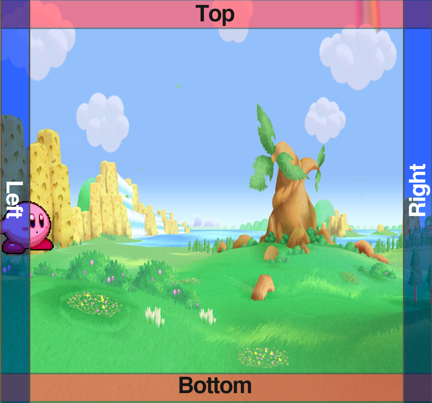
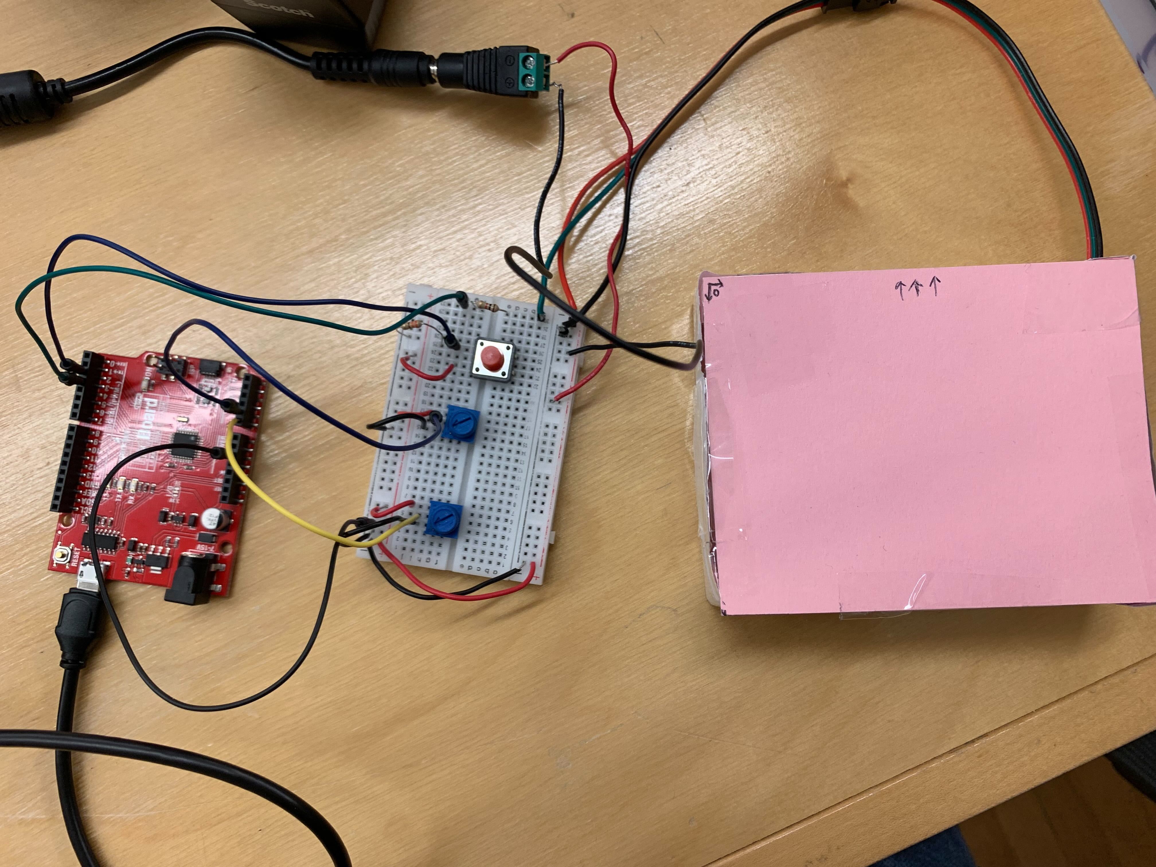
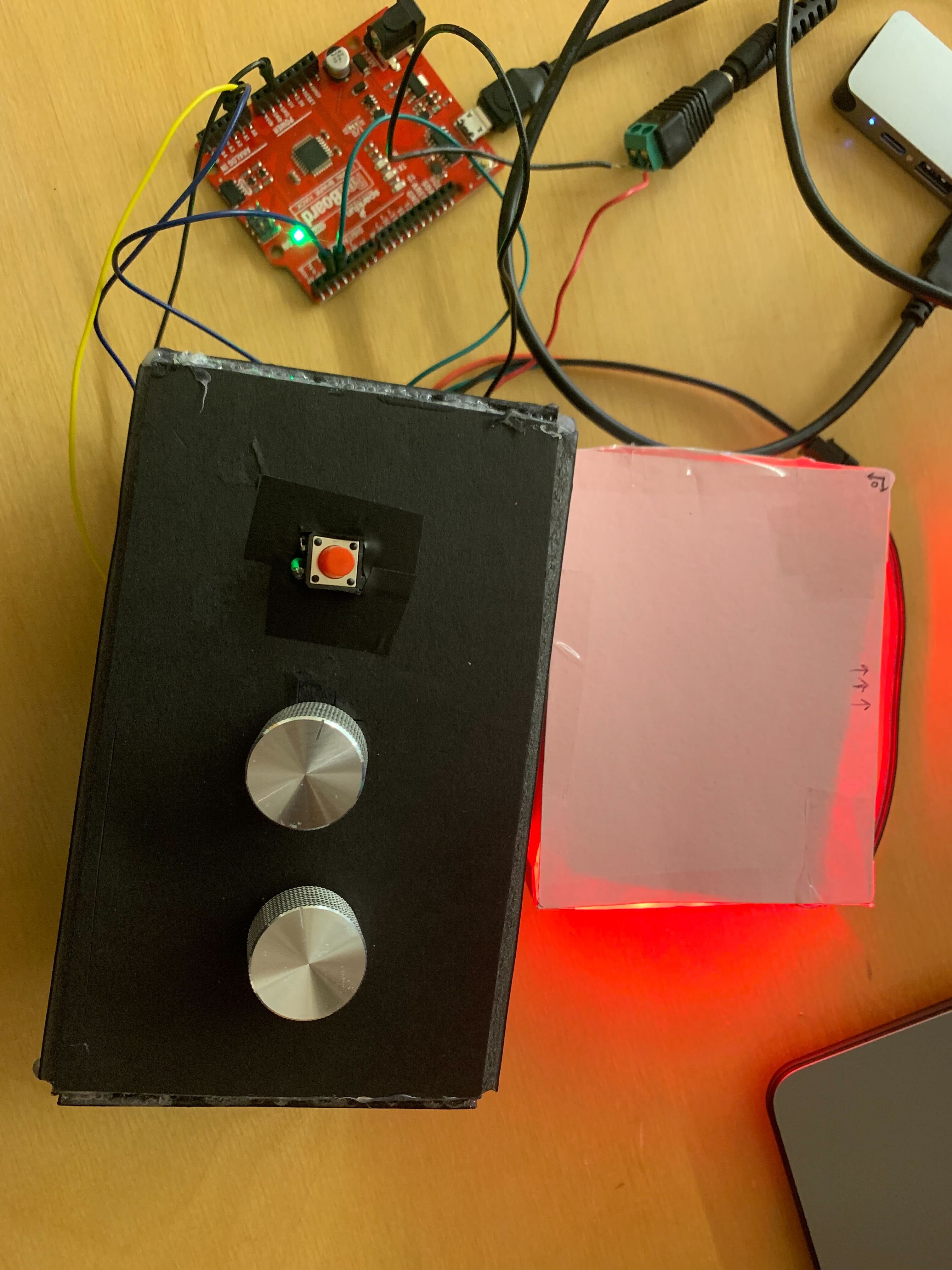
We created a 'light box', in which LED lights respond to Kirby's (Character) movement. When the Kirby on the monitor screen reaches the borders, the LED lights attached inside the borders of the box turn on corresponding to Kirby's position.
Arduino board, breadboard, resistor, LED strip, 2 POTs, 1 button, paper, tracing paper
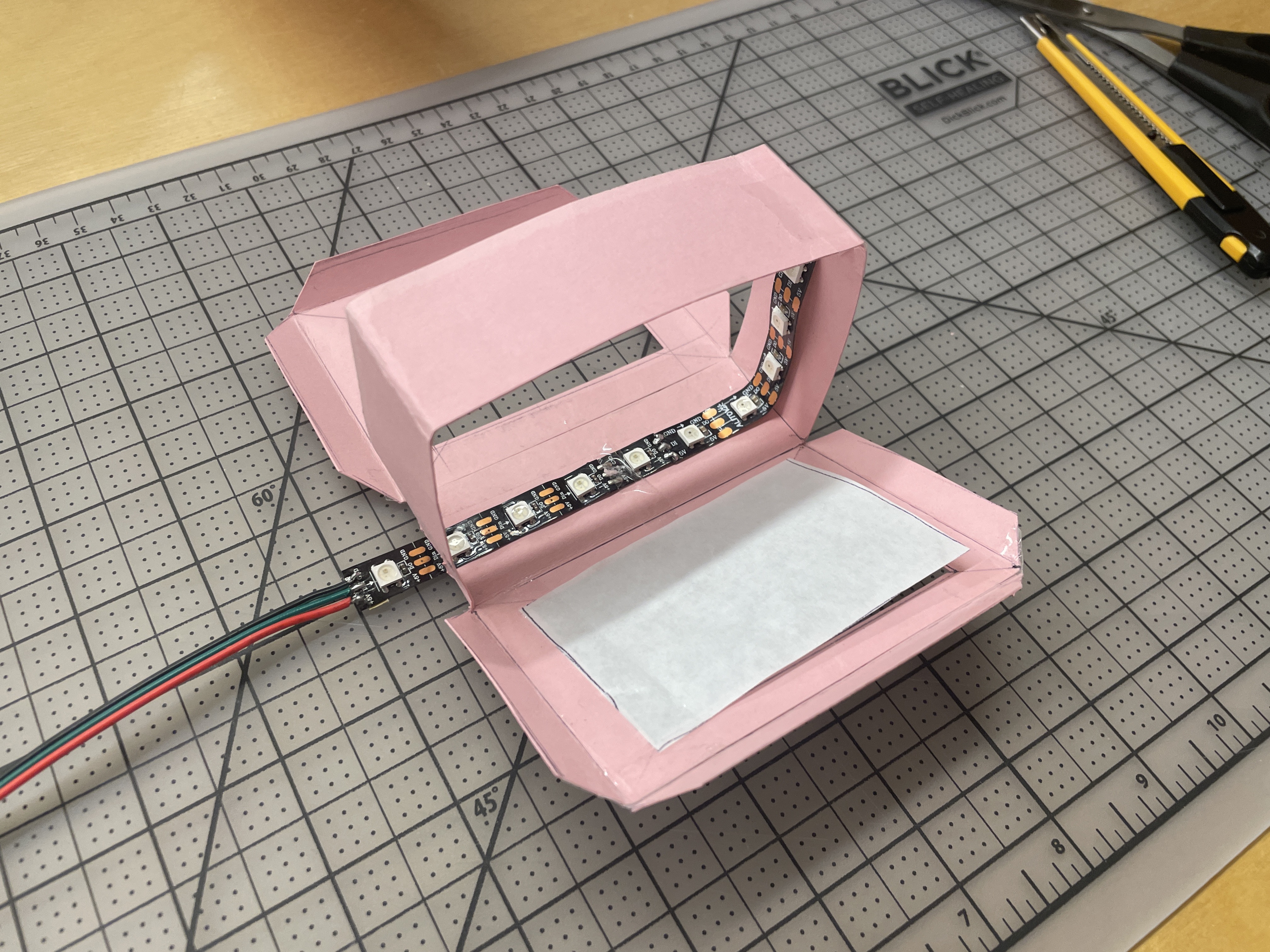

For the first draft of the box design, we attached the diffusion on the front sides of the box. However, while the LEDs are lighting up, it does not clearly indicate the left, right, top, and bottom sides of the borders. This is the reason why we fixed the box, changing the position of the diffusor from front to side.
// includeint sensorPin1 = A0; int sensorVal1; int sensorPin2 = A1; int sensorVal2; int sensorVal3 = 0; #define NUM_LEDS 20 #define DATA_PIN 3 CRGB leds[NUM_LEDS]; void setup() { Serial.begin(9600); while (Serial.available() <= 0) { Serial.println("hello"); delay(300); } FastLED.addLeds < WS2812, DATA_PIN, GRB >(leds, NUM_LEDS); pinMode(2, INPUT); } void loop() { sensorVal1 = analogRead(sensorPin1); sensorVal2 = analogRead(sensorPin2); if (Serial.available() > 0) { int inByte = Serial.read(); sensorVal1 = analogRead(sensorPin1); sensorVal1 = map(sensorVal1, 0, 1203, 0, 1000); sensorVal2 = analogRead(sensorPin2); sensorVal2 = map(sensorVal2, 0, 1203, 0, 1000); sensorVal3 = map(digitalRead(2), 0, 1, 0, 255); Serial.print(sensorVal1); Serial.print(","); Serial.print(sensorVal2); Serial.print(","); Serial.println(sensorVal3); } // // First, clear the existing led values if (sensorVal1 < 10){ fill_solid(leds +7, 4, CRGB::Red); //7-10 fill_solid(leds +16, 4, CRGB::Black); //16-19 if(digitalRead(2)==HIGH){ fill_solid(leds +7, 4, CRGB::Blue); //7-10 } } else if(850 < sensorVal1) { fill_solid(leds +7, 4, CRGB::Black); //7-10 fill_solid(leds +16, 4, CRGB::Red); //16-19 if(digitalRead(2)==HIGH){ fill_solid(leds +16, 4, CRGB::Blue); //16-19 }3 } else{ fill_solid(leds +7, 4, CRGB::Black); //7-10 fill_solid(leds +16, 4, CRGB::Black); //7-10 } ///SENSOR 2 (1-6, 11-16) if (sensorVal2 < 10){ fill_solid(leds +0, 6, CRGB::Red); //0-5 fill_solid(leds +10, 6, CRGB::Black); //10-15 if(digitalRead(2)==HIGH){ fill_solid(leds +0, 6, CRGB::Blue); //0-5 } } else if (850 < sensorVal2){ fill_solid(leds +0, 6, CRGB::Black); //0-5 fill_solid(leds +10, 6, CRGB::Red); //10-15 if(digitalRead(2)==HIGH){ fill_solid(leds +10, 6, CRGB::Blue); //10-15 } } else{ fill_solid(leds +0, 6, CRGB::Black); //0-5 fill_solid(leds +10, 6, CRGB::Black); //10-15 } FastLED.show(); }
let serial; // variable to hold an instance of the serialport library
let portName = '/dev/tty.usbserial-120'; // replace with your own port

let val1 = 0;
let val2 = 0;
let val3 = 0;
let kirby;
let lightbg;
let darkbg;


function preload(){
    kirby = loadImage('kurby.gif');
    lightbg = loadImage('bg1.jpg');
    darkbg = loadImage('bg2.jpg');
}

function setup() {
    createCanvas(windowWidth, windowHeight);

    // Serial setup

    serial = new p5.SerialPort();       // make a new instance of the serialport library
    serial.on('list', printList);  // callback to list all the ports
    serial.on('connected', serverConnected); // callback for connecting to server
    serial.on('open', portOpen);        // callback to check port opening
    serial.on('data', serialEvent);     // callback for when new data arrives
    serial.on('error', serialError);    // callback for errors
    serial.on('close', portClose);      // callback for the port closing

    serial.list();                      // list the serial ports
    serial.open(portName);              // open a serial port
    serial.write('x');
}

function draw() {
    // translate(val1, val2);

    if (val3 == 0){
            image (lightbg, 0,0,windowWidth,windowHeight);
    }
    else {
            image (darkbg, 0,0,windowWidth,windowHeight);
    }

    image (kirby, val1,val2,100,100);
}


// *** Serial

// get the list of ports:
function printList(portList) {
    // portList is an array of serial port names
    for (var i = 0; i < portList.length; i++) {
    // Display the list the console:
    console.log("port " + i + ": " + portList[i]);
    }
}

function serverConnected() {
    console.log('connected to server.');
}

function portOpen() {
    console.log('the serial port opened.')
}

function serialEvent() {
    let inString = serial.readStringUntil("\r\n");
    if (inString) {
    if (inString !== "hello") {
        let sensors = split(inString, ",");
        if (sensors.length > 1) {
        val1 = map(sensors[0], 0, 950, 0, width);
        val2 = map(sensors[1], 0, 950, 0, height);
        val3 = map(sensors[2], 0, 1, 0, 255);
        serial.write('x');
        console.log(val1,val2,val3);
        }
    }
    }
}

function serialError(err) {
    console.log('Something went wrong with the serial port. ' + err);
}

function portClose() {
    console.log('The serial port closed.');
}
Values from the soft linear potentiometer were not consistent and mapping them gave errors. We didn't understand why that happened;